Rockwell Automation Publication 8720MC-RM001K-EN-P - September 2018 33
Connector Data and Feature Descriptions Chapter 4
Internal Component Layout
There are references throughout this publication to the circuit boards and
other features identified in these drawings.
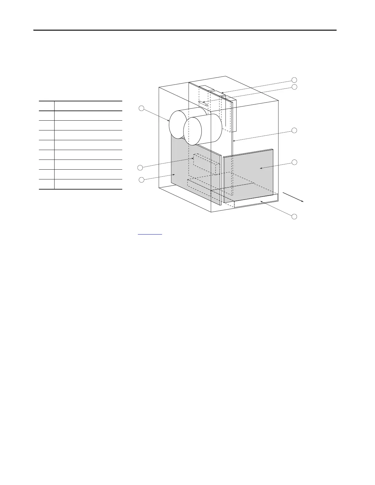
Figure 13 - 8720MC-RPS065 Internal Components
Figure 13 represents 8720MC-RPS065 (series #) unit, but the location of the
series B unit components is similar. Ribbon cables exist between the regulator
board (item 1) and the power interface board (item 2).
Item Internal Component
1 Regulator board (BDSR)
(1)
(1) Applies to only the leader unit.
2 Power interface board (PIFS)
3 Driver board (RCPB)
4 Bus capacitors
5 Cooling fan
6 Power modules
7Fuse - 1
8 Precharge/discharge resistor
 Loading...


