EasyManuals Logo
Home>Allen-Bradley>Controller>CompactLogix 5370 L1

Allen-Bradley CompactLogix 5370 L1 User Manual

Allen-Bradley CompactLogix 5370 L1
327 pages
To Next Page IconTo Next Page
To Previous Page IconTo Previous Page
Page #191 background imageLoading...
Page #191 background image
Rockwell Automation Publication 1769-UM021G-EN-P - October 2015 195
Use I/O Modules with CompactLogix 5370 L2 Controllers Chapter 8
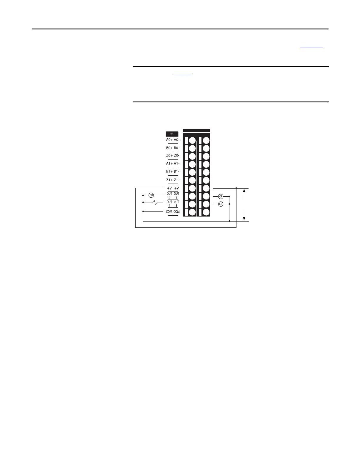
The embedded high-speed counter also supports four output points. Figure 37
shows a wiring diagram for the embedded high-speed counter output points.
Figure 37 - 1769-L27ERM-QBFC1B Controller Embedded High-speed Counter Output
Wiring Diagram
IMPORTANT
Figure 37 shows the embedded high-speed counter output points on the
1769-L27ER-QB1B controller. The embedded high-speed counter points on the
1769-L24ER-QBFC1B and 1769-L27ERM-QBFC1B controllers are organized and
wired the same.
+DC
5/24V DC
-DC

Table of Contents

Other manuals for Allen-Bradley CompactLogix 5370 L1

Questions and Answers:

Question and Answer IconNeed help?

Do you have a question about the Allen-Bradley CompactLogix 5370 L1 and is the answer not in the manual?

Allen-Bradley CompactLogix 5370 L1 Specifications

General IconGeneral
BrandAllen-Bradley
ModelCompactLogix 5370 L1
CategoryController
LanguageEnglish

Related product manuals