2-4 Configuring the 1203-GK5 Module or 1336-GM5 Board
Setting the Node Address
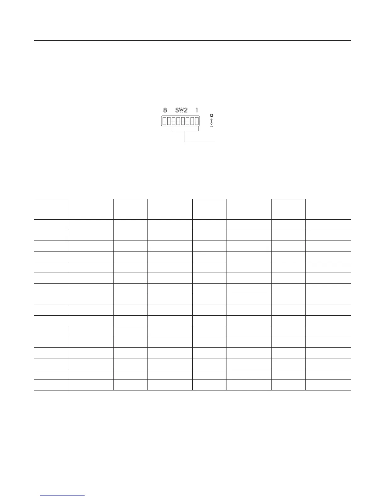
DIP switches 6 through 1 on SW2 set the node address for the
1203-GK5 module or 1336-GM5 board. The factory-default setting is
DeviceNet node address 63.
Figure 2.3
Setting the Node Address
To edit the node address, you need to:
1. Refer to the following table to determine the switch settings:
2. Slide switches 6 through 1 to their appropriate positions.
Important: DIP switch and parameter settings take effect when a
module or board first receives power. When you change a setting, you
must remove and then reapply power for the new setting to take
effect.
Off = 0
On = 1
Use DIP switches 6
through 1 for setting
the node address.
DeviceNet
Address
Switch Setting
6 <---- 1
DeviceNet
Address
Switch Setting
6 <---- 1
DeviceNet
Address
Switch Setting
6 <---- 1
DeviceNet
Address
Switch Setting
6 <---- 1
0 000000 16 010000 32 100000 48 110000
1 000001 17 010001 33 100001 49 110001
2 000010 18 010010 34 100010 50 110010
3 000011 19 010011 35 100011 51 110011
4 000100 20 010100 36 100100 52 110100
5 000101 21 010101 37 100101 53 110101
6 000110 22 010110 38 100110 54 110110
7 000111 23 010111 39 100111 55 110111
8 001000 24 011000 40 101000 56 111000
9 001001 25 011001 41 101001 57 111001
10 001010 26 011010 42 101010 58 111010
11 001011 27 011011 43 101011 59 111011
12 001100 28 011100 44 101100 60 111100
13 001101 29 011101 45 101101 61 111101
14 001110 30 011110 46 101110 62 111110
15 001111 31 011111 47 101111 63 111111
efesotomasyon.com - Allen Bradley,Rockwell,plc,servo,drive
 Loading...


