Configuring the 1203-GK5 Module or 1336-GM5 Board 2-5
Setting the Data Rate
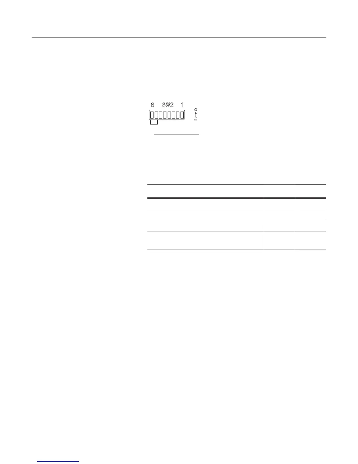
DIP switches 7 and 8 on SW2 set the data rate at which the 1203-GK5
module or 1336-GM5 board communicates on the network. The
factory-default setting for the data rate is 125K.
Figure 2.4
Setting the Data Rate
To edit the data rate, you need to:
1. Refer to the following table to determine the switch settings.
2. Slide switches 8 and 7 to their appropriate positions.
Important: DIP switch and parameter settings take effect when a
module or board first receives power. When you change a setting, you
must remove and then reapply power for the new setting to take
effect.
Data Rate Switch 2-8 SW2-7
125K 0 0
250K 0 1
500K 1 0
Module uses Node Address and
Data Rate internally programmed.
➀ ➁
11
➀
When the switches are set to this position, the communications module data rate and
node address can be programmed over DeviceNet using the DN-NV-Node Adx and
DN-NV-Data Rate parameters. For instructions on using DeviceNet Manager to edit
parameters, refer to “Viewing and Editing Parameters” on page 4-20.
➁
To enable the faulted node recovery feature, SW2-8 and SW2-7 must both be set to On.
Off = 0
On = 1
Use DIP switches
8 and 7 for setting
the data rate.
efesotomasyon.com - Allen Bradley,Rockwell,plc,servo,drive
 Loading...


