FLEX I/O Digital DC Output Modules 7
Publication 1794-IN094C-EN-P - July 2015
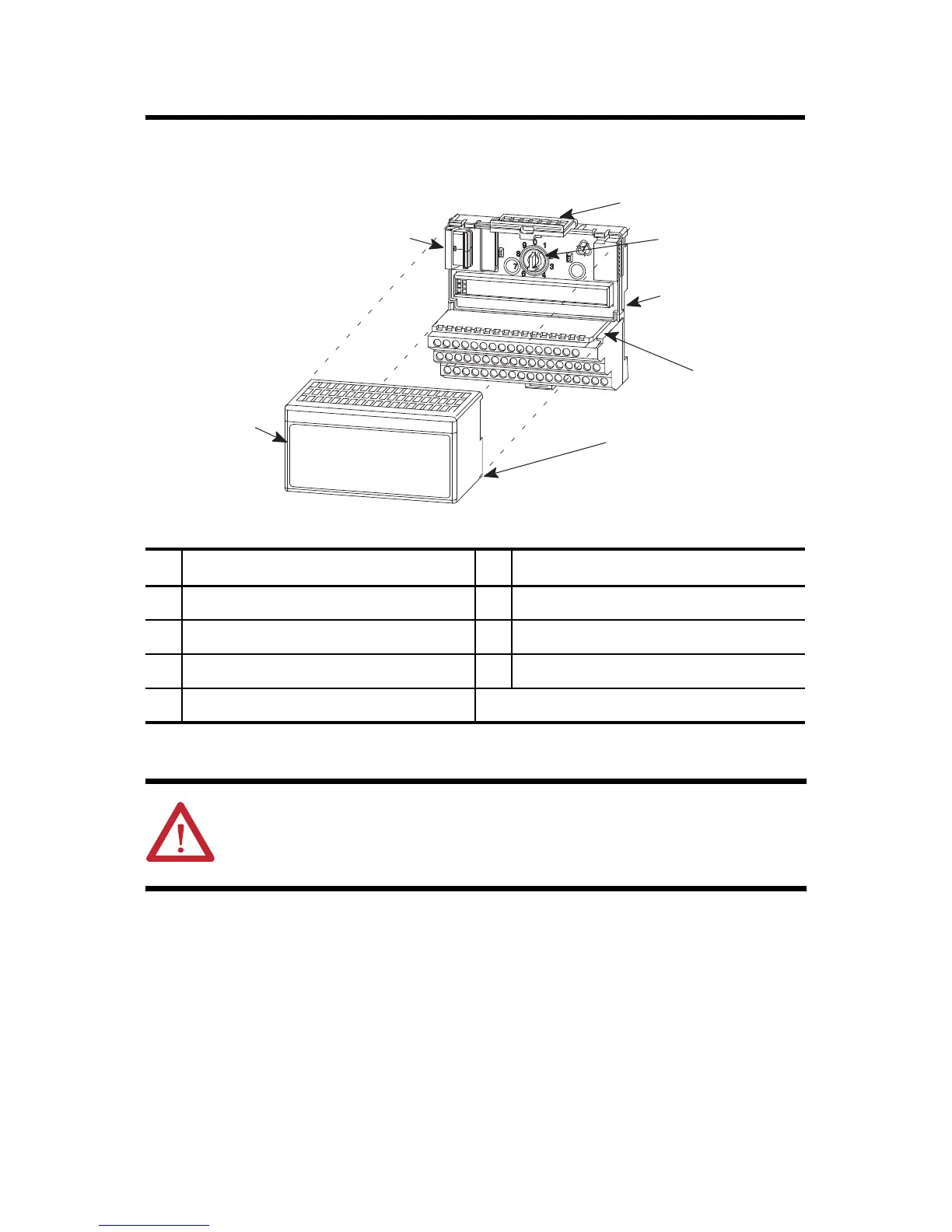
Installing Your Digital Output Module
The module mounts on a 1794 terminal base.
1. Rotate the keyswitch (1) on the terminal base (2) clockwise to position 2 as
required for this type of module.
2. Make certain the flexbus connector (3) is pushed all the way to the left to connect
with the neighboring terminal base/adapter. You cannot install the module
unless the connector is fully extended.
Description Description
1 Keyswitch 5 Alignment bar
2 Terminal base 6 Groove
3 Flexbus connector 7 Latching mechanism
4 Module
ATTENTION: During mounting of all devices, be sure that all debris (metal
chips, wire strands, etc.) is kept from falling into the module. Debris that falls
into the module could cause damage on power up.
1
2
3
4
5
6
7

 Loading...


