FLEX I/O Digital DC Output Modules 15
Publication 1794-IN094C-EN-P - July 2015
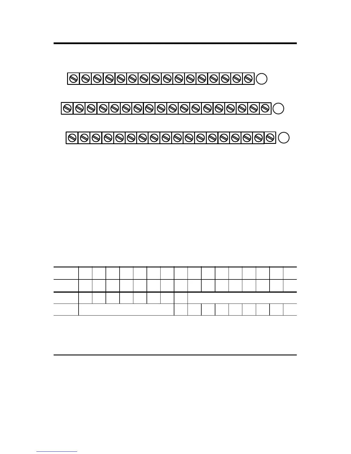
1794-TB32 and 1794-TB32S Terminal Base Wiring for 1794-OB32PI
Configuring your 1794-OB8EP Output Module
You configure your output module by setting bits in the configuration word (see below).
Image Table Memory Map for the 1794-OB8EP Module
Dec 1514131211109876 543210
Oct 17161514131211107 6 5 4 3 2 1 0
Read F7 F6 F5 F4 F3 F2 F1 F0 Reserved (see note)
Write Not used FR O7 O6 O5 O4 O3 O2 O1 O0
Where O = Output – O0 corresponds to output 0, O1 corresponds to output 1, and so on.
F = Overload fault bit – 1 = fault present; 0 = no fault
FR = Fault reset bit – 1 = reset output; 0 = no change
Note: The unused lower byte in read word 1 floats during operation. Do not use this byte for fault status. See
Programming below.
17 18 19 20 21 22 23 24 25 26 27 28 29 30 31 32 33
0 1 2 3 4 5 6 7 8 9 10 11 12 13 14 15
16
35 36 37 38 39 40 41 42 43 44 45 46 47 48 49 50 51
34
NC
+V2 = Terminals 43, 45, 47 and 49
Outputs
Outputs
+V1 COM1 +V1 COM1 +V1 COM1 +V1 COM1 +V2 COM2 +V2 COM2 +V2 COM2 +V2 COM2 NC
+V1 = Terminals 35, 37, 39 and 41
COM1 = Terminals 36, 38, 40 and 42
NC = No connections (terminals 16, 33, 34 and 51)
COM2 = Terminals 44, 46, 48 and 50
NC NC
(1794-TB32 shown)
A
B
C

 Loading...


