28 Rockwell Automation Publication CC-QS038A-EN-P - August 2015
Chapter 2 System Validation
Validate Your System
In this section, you review the Machine Functions screen and explore the Status and Command screens to test the manual
control of the building block.
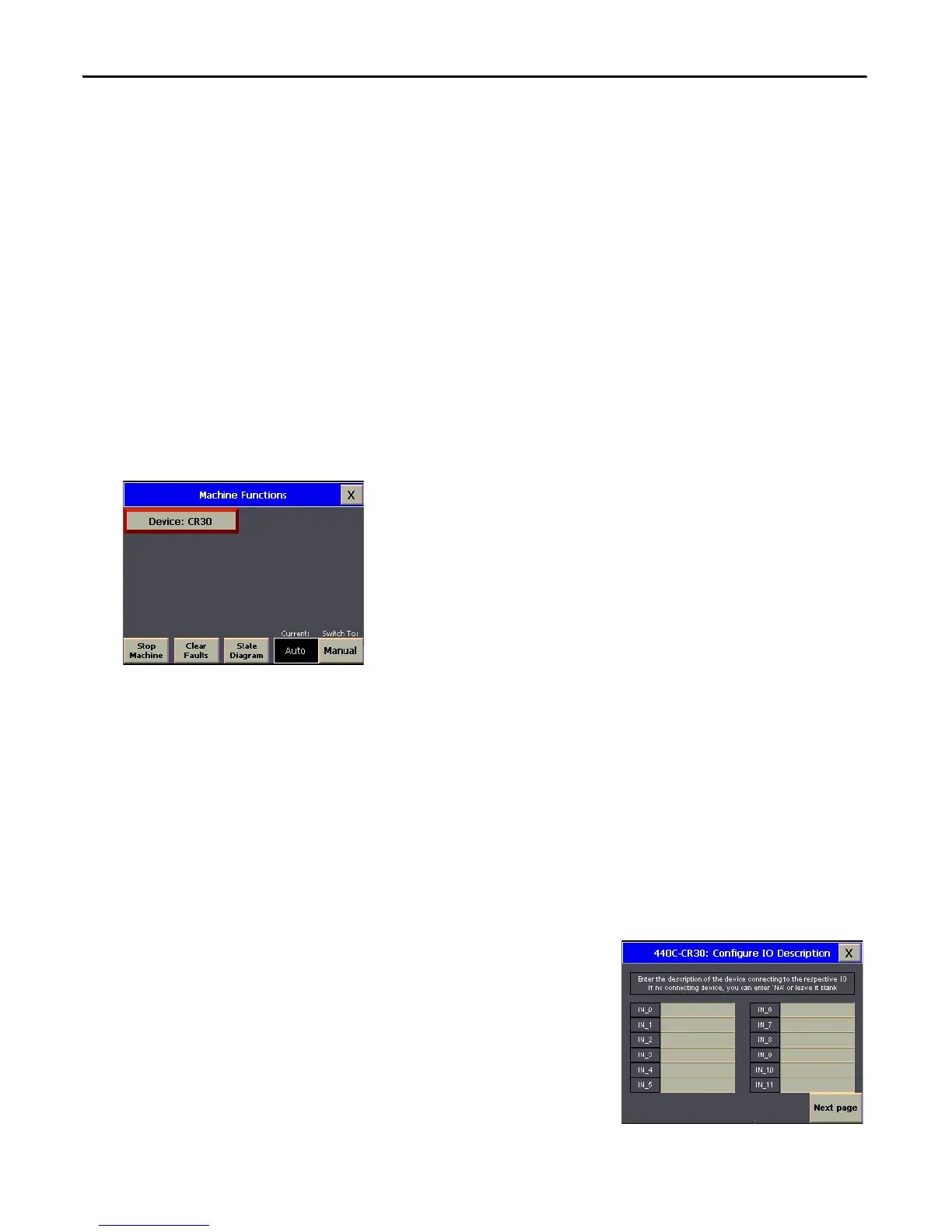
Understand the Machine Functions Screen
The Machine Functions screen is the screen that links to the installed building blocks. When this screen is first loaded, you
can complete the following tasks:
• Return to the Machine Overview screen by pressing the X in the upper right-hand corner of the screen.
• View a device in detail by pressing its button.
• View the current machine Auto/Manual state.
• Change the current machine Auto/Manual state.
• Clear machine faults, start/stop the machine (while in Auto mode), and go to the machine state diagram overview
screen.
The border of the device button changes color to indicate a specific status. For the 440C-CR30 safety relay, the button
border colors indicate the following status:
• A green border indicates that the safety relay is active and operating.
• A gray border indicates that the safety relay is inactive and stopped.
• A red border indicates that there is a fault, or an alarm is present.
Set Up the Configuration Screen
To set up the 440C-CR30: Configure IO Description screen, follow these steps.
1. From the Machine Functions screen, switch the Operation mode to
Manual.
2. Press the device.
The Configuration screen for the device appears. There are a total of four
configuration screens.
3. Type the name of each terminal of the 440C-CR30 safety relay.
There are a total of 22 embedded terminals and two plug-in terminals.
4. Record a description of each connection in the table on the next page.

 Loading...


