14 Kinetix 5500 Servo Drives
Rockwell Automation Publication 2198-IN001C-EN-P - January 2014
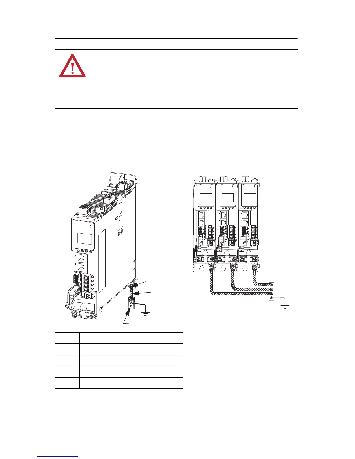
Ground Your Kinetix 5500 Drive to the Subpanel
Ground Kinetix 5500 drives and 2198-CAPMOD-1300 capacitor modules to a bonded cabinet
ground bus with a braided ground strap or 4.0 mm
2
(12 AWG) copper wire.
Connecting the Braided Ground Strap
ATTENTION: To avoid personal injury and/or equipment damage, observe the following:
• Make sure installation complies with specifications regarding wire types, conductor sizes,
branch circuit protection, and disconnect devices. The National Electrical Code (NEC) and local
codes outline provisions for safely installing electrical equipment.
• Use motor power connectors only for connection purposes. Do not use them to turn the unit on
and off.
• Ground shielded power cables to prevent potentially high voltages on the shield.
Item Description
1 Ground screw (green) 2.0 N•m (17.5 lb•in), max
2 Braided ground strap (customer supplied)
3 Ground grid or power distribution ground
4 Bonded cabinet ground bus (customer supplied)
4
3
2
1
Kinetix 5500
Servo Drive
(standalone)
Kinetix 5500
Servo Drives
(shared-bus)

 Loading...


