12 Kinetix 5500 Servo Drives
Rockwell Automation Publication 2198-IN001C-EN-P - January 2014
Safe Torque Off (STO) Connector Pinout
The 2198-Hxxx-ERS drives ship with the safe torque-off function enabled. Connect the safe
torque-off inputs to a safety circuit or install bypass wiring to enable motion. Refer to the
Kinetix 5500 Servo Drives User Manual, publication 2198-UM001, for more information.
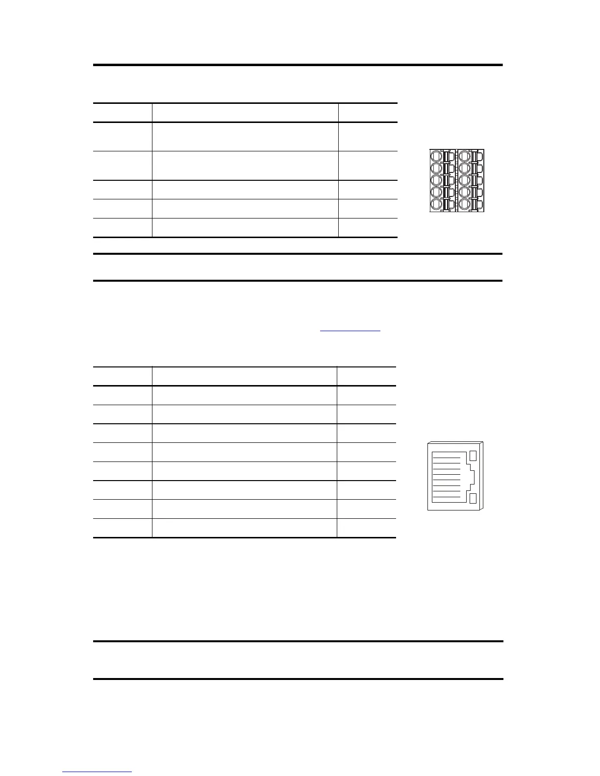
Ethernet Communication PORT1 and PORT2 Pinout
Wiring Requirements
Wire must be copper with 75 °C (167 °F) minimum rating. Phasing of mains AC power is
arbitrary and earth ground connection is required for safe and proper operation.
STO Pin Description Signal
1
Safety bypass plus signal. This signal is jumped to the
safety inputs to enable motion without safety
SB+
2
Safety bypass minus signal. This signal is jumped to
safety common to enable motion without safety
SB-
3 Safe-stop input channel 1 S1
4 Safe-stop input common SC
5 Safe-stop input channel 2 S2
The safe torque-off (STO) connector applies to only the 2198-Hxxx-ERS drives.
Port Pin Description Signal
1 Transmit port (+) data terminal + TX
2 Transmit port (-) data terminal - TX
3 Receive port (+) data terminal + RX
4– –
5– –
6 Receive port (-) data terminal - RX
7– –
8– –
The National Electrical Code and local electrical codes take precedence over the values and
methods provided.
Pin 1
1
8

 Loading...


