Kinetix 5500 Servo Drives 7
Rockwell Automation Publication 2198-IN001C-EN-P - January 2014
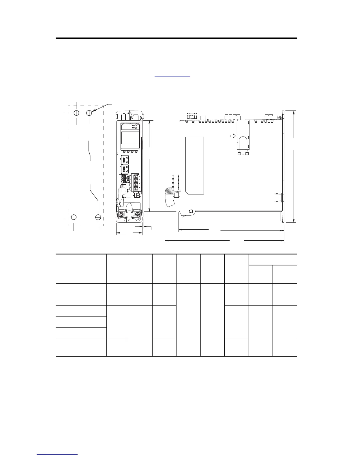
Product Dimensions
Included in this figure are the drill hole patterns for standalone drives. Refer to the Kinetix 5500
Servo Drives User Manual, publication 2198-UM001
, for multi-axis drill-hole patterns.
Kinetix 5500 Drives with 2198-KITCON-DSL Connector Kit
Kinetix 5500 Drive
Cat. No.
Frame
A
mm (in.)
B
mm (in.)
C
mm (in.)
D
mm (in.)
E
mm (in.)
Drill Hole Patterns
F
mm (in.)
G
mm (in.)
2198-H003-ERSx
1 50 (1.97)
170
(6.69)
200
(7.87)
226
(8.90)
215
(8.46)
193.68
(7.62)
4.51
(0.18)
2198-H008-ERSx
2198-H015-ERSx
2 55 (2.16)
225
(8.86)
265
(10.43)
243.84
(9.60)
5.00
(0.20)
2198-H025-ERSx
2198-H040-ERSx
2198-H070-ERSx 3
85.2
(3.35)
250
(9.84)
294
(11.57)
273.70
(10.78)
0.0
E
D
C
A
3.0
(0.12)
B
F
0.0
0.0
G
52.50
(2.07)
34.00
(1.34)
Ø M4 (#8-32)
Dimensions are in mm (in.)
2198-H003-ERS
Drive is Shown
Applies to
Only
Frame 3

 Loading...


