Kinetix 5500 Servo Drives 15
Rockwell Automation Publication 2198-IN001C-EN-P - January 2014
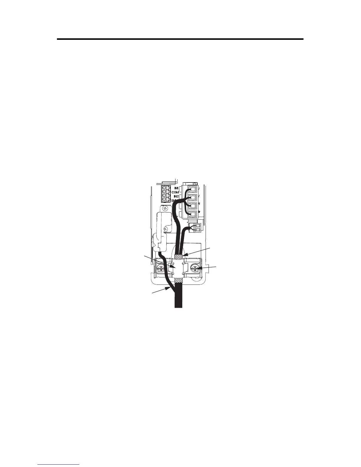
Attach the Motor Cable Shield Clamp
A shield clamp and two screws are supplied with each Kinetix 5500 drive. Use the clamp to bond
the motor cable shield-braid to chassis ground.
• Routing the conductors with service loops provides stress relief.
• Make sure the cable clamp tightens around the cable shield and provides a good bond
between the cable shield and the drive chassis.
Kinetix VP Servo Motors
Kinetix VP motors have single cable technology and use the 2198-KITCON-DSL connector kit
with 2090-CSxM1DF-xxAxxx motor cables. Route conductors as shown in theses examples.
18 AWG Cable Installation
Motor Cable
Shield Clamp
2198-KITCON-DSL
Motor Feedback
Connector Kit
Motor Power
(MP) Connector
Motor Brake
(BC) Connector
Exposed shield braid
under clamp.
Feedback cable routed
around the shield clamp.
Shield Clamp Screws (2)
2.0 N•m (17.7 lb•in), max
Kinetix 5500 Servo Drives,
Frame 1 or 2, Front View
(frame 1 is shown)
Bulletin 2090 Single Motor Cable

 Loading...


