Kinetix 5500 Servo Drives 17
Rockwell Automation Publication 2198-IN001C-EN-P - January 2014
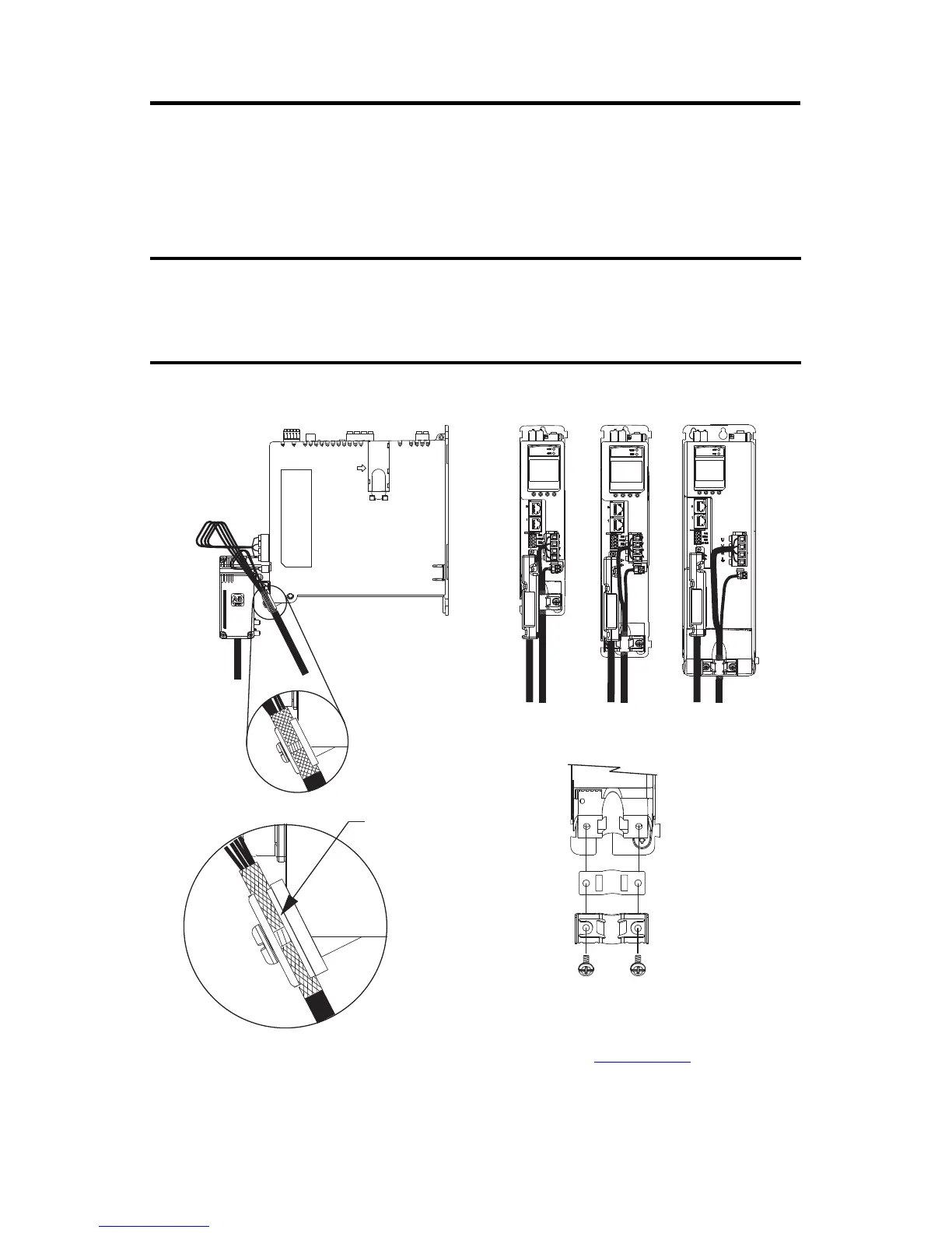
Other Allen-Bradley Motors and Actuators
For other compatible Allen-Bradley motors and actuators, use the 2198-H2DCK converter kit
for wiring motor feedback. A clamp spacer is included with the kit for motor power/brake cable
diameters that are too small for a tight fit within the drive clamp alone.
Cable Clamp Attachment
Refer to the Kinetix 5500 Servo Drives User Manual, publication 2198-UM001, for detailed
information on wiring the 2198-H2DCK feedback converter kit and attaching the motor
power/brake shield clamp.
If the power/brake cable shield has a loose fit inside the shield clamp, insert the clamp spacer
between the shield clamp and the drive to reduce the clamp diameter. When the clamp screws
are tight, 2.0 N•m (17.7 lb•in), the result must be a high-frequency bond between the cable
shield and the drive chassis.
Clamp Compressed
Around Shield
(no spacer required)
Insert the clamp spacer when the
cable diameter is smaller than the
drive clamp alone.
Servo Drive
Clamp Spacer (if needed)
Shield Clamp
Clamp Screws
2.0 N•m (17.7 lb•in.)
Service Loops
Frame 1
Servo Drive
Frame 2
Servo Drive
Frame 3
Servo Drive
Clamp Spacer Added
(small diameter cable)

 Loading...


