Kinetix 5500 Servo Drives 11
Rockwell Automation Publication 2198-IN001C-EN-P - January 2014
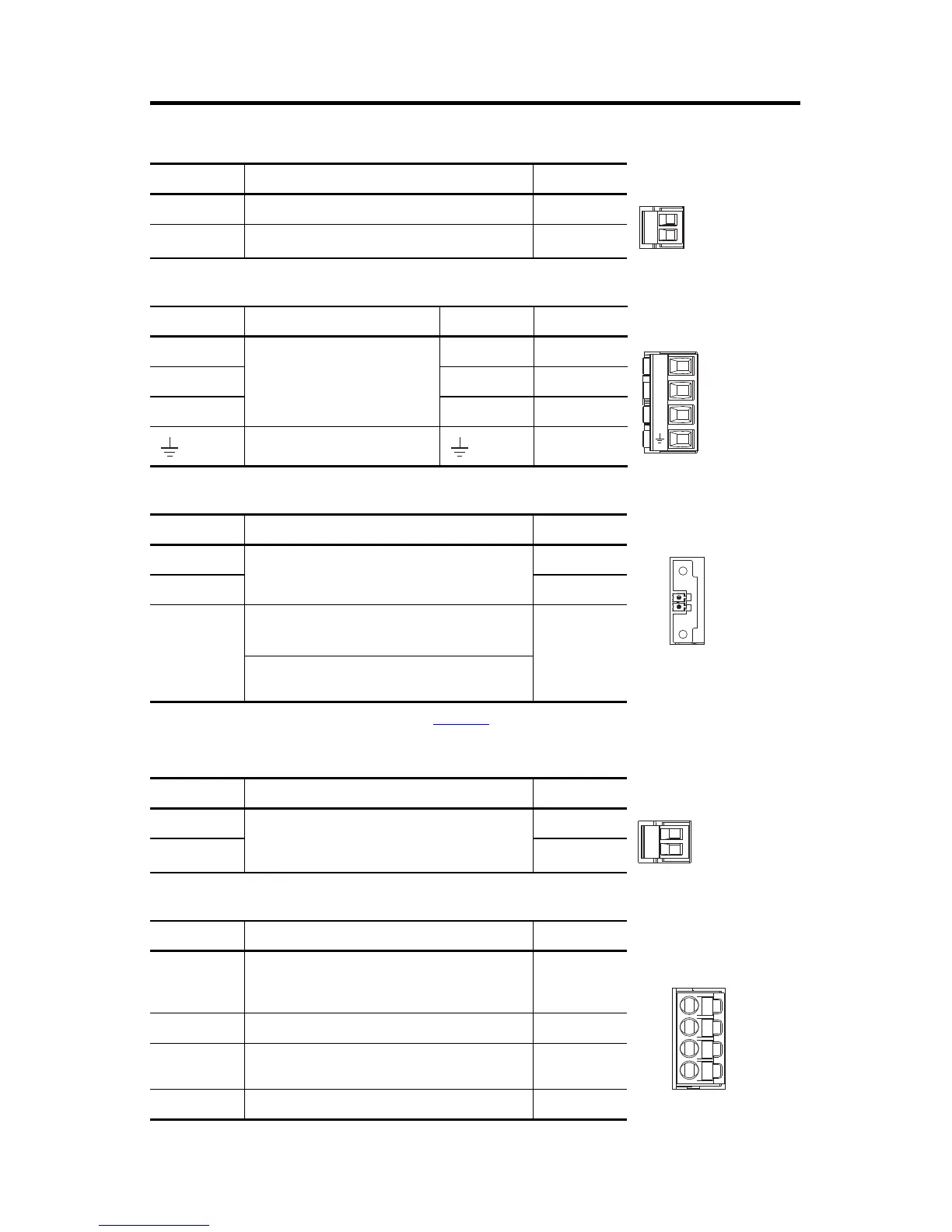
Control Input Power (CP) Connector Pinout
Motor Power (MP) Connector Pinout
Motor Feedback (MF) Connector Pinout
Motor Brake (BC) Connector Pinout
Digital Inputs (IOD) Connector Pinout
CP Pin Description Signal
1 24V power supply, customer-supplied 24V+
224V common 24V-
MP Pin Description Signal Color
U
Three-phase motor power
UBrown
VVBlack
WWBlue
Chassis ground Green
MF Pin
(1)
(1) Refer to Kinetix 5500 Servo Drives User Manual, publication 2198-UM001, for installation instructions.
Description Signal
1
Bidirectional data and power for digital encoder
interface
D+
2D-
SHIELD
Cable shield and grounding plate (internal to
2198-KITCON-DSL connector kit) termination point
SHIELD
Cable shield and shield clamp (internal to 2198-H2DCK
converter kit) termination point
BC Pin Description Signal
1
Motor brake connections
MBRK+
2MBRK-
IOD Pin Description Signal
1
High-speed Registration/Home position input. A
low/high or high/low transition triggers a registration
event. This is a dual-function input.
IN1
(1)
(1) This signal has dual-functionality. You can use IN1 (IOD-1) as registration or Home input.
2 I/O common for customer-supplied 24V supply. COM
3
High speed registration input. A low/high or high/low
transition triggers a registration event.
IN2
4 I/O cable shield termination point. SHLD
U
V
W
2
1

 Loading...


