10 Kinetix 5500 Servo Drives
Rockwell Automation Publication 2198-IN001C-EN-P - January 2014
Kinetix 5500 Drive Connectors
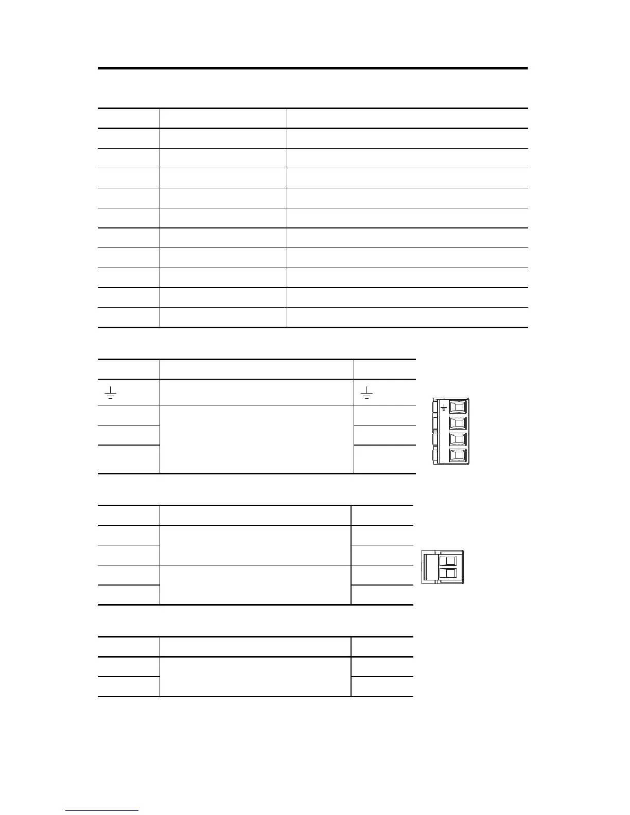
Mains Input Power (IPD) Connector
Shunt Power (RC) Connector Pinout
DC Bus (DC) Connector Pinout
Designator Description Connector
IPD AC mains input power 4-position plug, terminal screws
DC DC common bus power 2-position (T-connector used in shared-bus configurations)
CP 24V control input power 2-position plug, terminal screws
RC Shunt power 2-position plug, terminal screws
MP Motor power 4-position plug, terminal screws
MF Motor feedback 2-position plug, spring terminals
BC Brake power 2-position plug, terminal screws
IOD Digital inputs 4-position plug, spring terminals
STO Safe torque off 5-position plugs, spring terminals, 2x (2 rows of 5 pins)
PORT1, PORT2 Ethernet communication ports RJ45 Ethernet
IPD Pin Description Signal
Chassis ground
L3
Three-phase input power
L3
L2 L2
L1 L1
RC Pin Description Signal
1
Shunt connections (frames 2 and 3)
DC+
2SH
1
Shunt connections (frame 1)
SH
2DC+
DC Pin Description Signal
1
DC bus connections
DC-
2DC+
L3
L2
L1

 Loading...


