Publication 1762-RM001C-EN-P
1-12 I/O Configuration
Specialty I/O Configuration
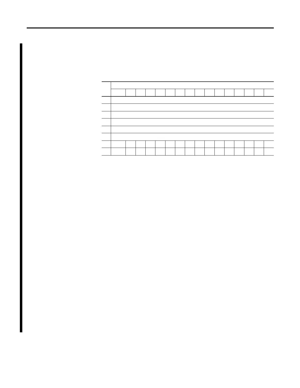
1769-IT6 Thermocouple Module Input Data File
The input data file contains the analog values of the inputs.
The bits are defined as follows:
•
Sx = General status bit for channels 0 through 5 and CJC sensors (S6
and S7). This bit is set (1) when an error (over-range, under-range,
open-circuit, or input data not valid) exists for that channel. An input
data not valid condition is determined by the user program. This
condition occurs when the first analog-to-digital conversion is still in
progress, after a new configuration has been sent to the module.
•
OCx = Open circuit detection bits indicate an open input circuit on
channels 0 through 5 (OC0 through OC5) and on CJC sensors CJC0
(OC6) and CJC1 (OC7). The bit is set (1) when an open-circuit
condition exists.
•
Ux = Under-range flag bits for channels 0 through 5 and the CJC
sensors (U6 and U7). For thermocouple inputs, the under-range bit is
set when a temperature measurement is below the normal operating
range for a given thermocouple type. For millivolt inputs, the
under-range bit indicates a voltage that is below the normal operating
range. These bits can be used in the control program for error
detection.
•
Ox = Over-range flag bits for channels 0 through 5 and the CRC
sensors (O6 and O7). For thermocouple inputs, the over-range bit is
set when a temperature measurement is above the normal operating
range for a given thermocouple type. For millivolt inputs, the
over-range bit indicates a voltage that is above the normal operating
range. These bits can be used in the control program for error
detection.
Word
Bit Position
15 14131211109876543210
0 Analog Input Data Channel 0
1 Analog Input Data Channel 1
2 Analog Input Data Channel 2
3 Analog Input Data Channel 3
4 Analog Input Data Channel 4
5 Analog Input Data Channel 5
6 OC7 OC6 OC5 OC4 OC3 OC2 OC1 OC0 S7 S6 S5 S4 S3 S2 S1 S0
7 U0 O0U1U0U2O2U3O3U4O4U5O5U6O6U7O7

 Loading...


