Publication 1762-RM001C-EN-P
ASCII Instructions 20-13
Addressing Modes and File Types can be used as shown below:
Example
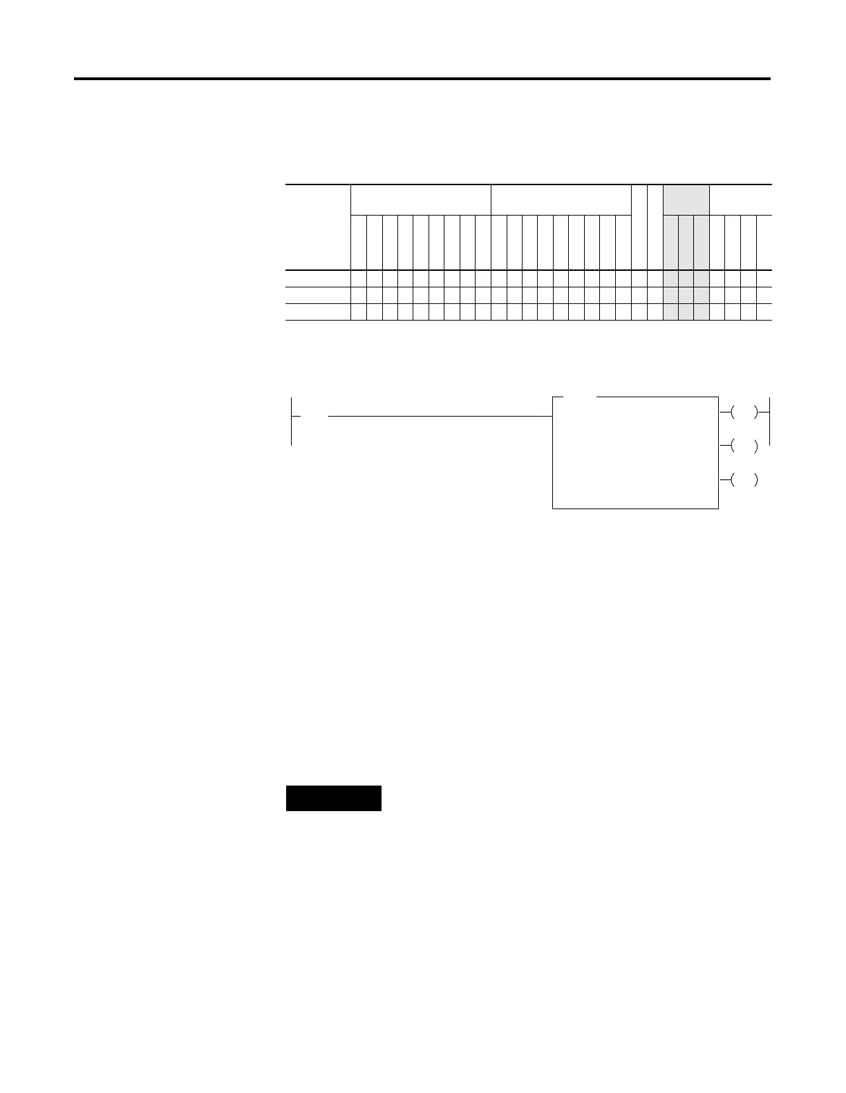
In this example, when the rung goes from false-to-true, the control
element Enable (EN) bit is set. When the instruction is placed in the ASCII
queue, the Queue bit (EU) is set. The Running bit (RN) is set when the
instruction is executing. The DN bit is set on completion of the
instruction.
Forty characters from string ST37:40 are sent through channel 0. The
Done bit (DN) is set and a value of 40 is present in the POS word of the
ASCII control data file.
When an error is detected, the error code is written to the Error Code Byte
and the Error Bit (ER) is set. See ASCII Instruction Error Codes on
page 20-30 for a list of the error codes and recommended action to take.
Table 20.10 AWT Instruction Valid Addressing Modes and File Types
For definitions of the terms used in this table see Using the Instruction Descriptions on page4-2.
Parameter
Data Files
(1)
(1) The Control data file is the only valid file type for the Control Element.
Function Files
CS - Comms
IOS - I/O
Address
Mode
Address
Level
O
I
S
B
T, C, R
N
ST
L
MG, PD
RTC
HSC
PTO, PWM
STI
EII
BHI
MMI
DAT
TPI
Immediate
Direct
Indirect
Bit
Word
Long Word
Element
Channel • •
Source •
• •
Control •
• •
AWT
ASCII WRITE
Channel
Source
I:1
10
[
[
Control
0
ST37:20
R6:23
String Length
Characters Sent
40
0
0
EN
DN
ER
Error
If input slot 1, bit 10 is set, write 40 characters from
ST37:20 to the display device.
NOTE
For information on the timing of this instruction, see the
timing diagram on page 20-28.

 Loading...


