Publication 1762-RM001C-EN-P
ASCII Instructions 20-21
•
AND Mask is the mask used to reset the RTS control line. Bit 1
corresponds to the RTS control line. A value of “1” in the AND mask
resets the RTS control line; a value of “0” leaves the line unchanged.
The valid data range for the mask is from 0000 to FFFF hexadecimal.
•
OR Mask is the mask used to set the RTS control line. Bit 1
corresponds to the RTS control line. A value of “1” in the OR mask
sets the RTS control line; a value of “0” leaves the line unchanged. The
valid data range for the mask is from 0000 to FFFF hexadecimal.
•
Control is the control data file. See page 20-6.
•
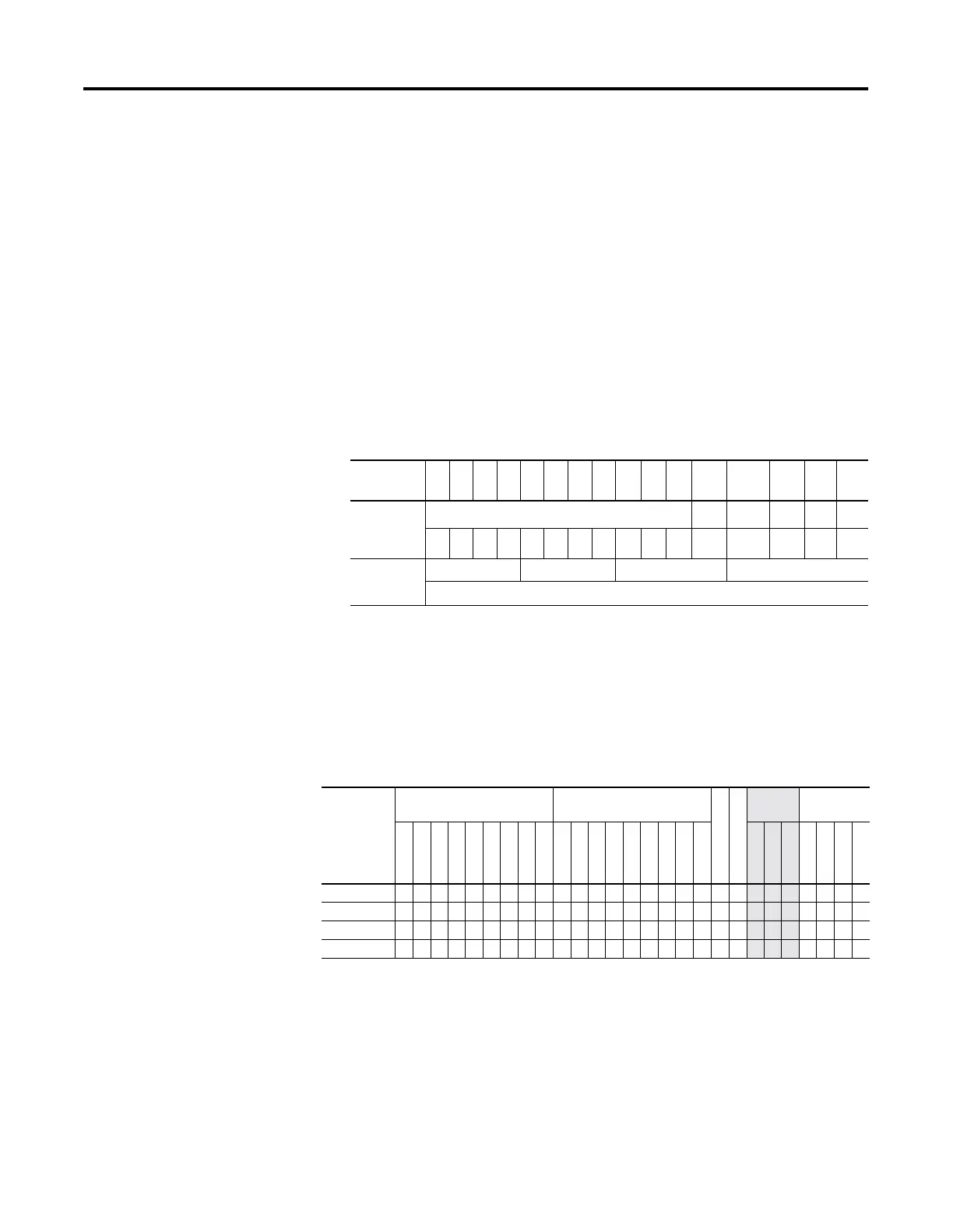
Channel Status displays the current status (0000 to 001F) of the
handshake lines for the specified channel. This status is read-only and
resides in the .POS field in the control data file. The following shows
how to determine the channel status value. In this example, the value
is 001F.
•
Error displays the hexadecimal error code that indicates why the ER
bit was set in the control data file. See page 20-30 for error code
descriptions.
Addressing Modes and File Types can be used as shown below:
Instruction Operation
This instruction executes on either a false or true rung. However a
false-to-true rung transition is required to set the EN bit to repeat the
instruction.
Channel
Status Bit
15 14 13 12 11 10 9 8 7 6 5 4 3 2 1 0
Handshake
Control Line
Setting
reserved --
DCD
(1)
(1) The DCD handshake line is only supported on Channel 1.
-- RTS CTS
000000000001 1 1 1 1
Channel
Status
001 F
Word 2 of the Control Element = 001F
Table 20.22 AHL Instruction Valid Addressing Modes and File Types
For definitions of the terms used in this table see Using the Instruction Descriptions on page4-2.
Parameter
Data Files
(1)
(1) The Control data file is the only valid file type for the Control Element.
Function Files
CS - Comms
IOS - I/O
Address
Mode
Address
Level
O
I
S
B
T, C, R
N
ST
L
MG, PD
RTC
HSC
PTO, PWM
STI
EII
BHI
MMI
DAT
TPI
Immediate
Direct
Indirect
Bit
Word
Long Word
Element
Channel • •
AND Mask •• •••
• • •
OR Mask •• •••
• • •
Control •
• •

 Loading...


