1 Publication 1762-RM001C-EN-P
Chapter
21
Communications Instructions
This chapter contains information about the Message (MSG) and Service
Communications (SVC), communication instructions. This chapter
provides information on:
•
how messaging works
•
what the instructions look like
•
how to configure and use the instructions
•
examples and timing diagrams
The communication instructions read or write data to another station.
Messaging Overview
The communication architecture is comprised of three primary
components:
•
Ladder Scan
•
Communications Buffers
•
Communication Queue
These three components determine when a message is transmitted by the
controller. For a message to transmit, it must be scanned on a true rung of
logic. When scanned, the message and the data defined within the
message (if it is a write message) are placed in a communication buffer.
The controller continues to scan the remaining user program. The
message is processed and sent out of the controller via the
communications port after the ladder logic completes, during the Service
Communications part of the operating cycle, unless an SVC is executed.
If a second message instruction is processed before the first message
completes, the second message and its data are placed in one of the three
remaining communication buffers. This process repeats whenever a
message instruction is processed, until all four buffers are in use.
When a buffer is available, the message and its associated data are placed
in the buffer immediately. If all four buffers for the channel are full when
the next (fifth) message is processed, the message request, not the data, is
placed in the channel’s communications queue. The queue is a message
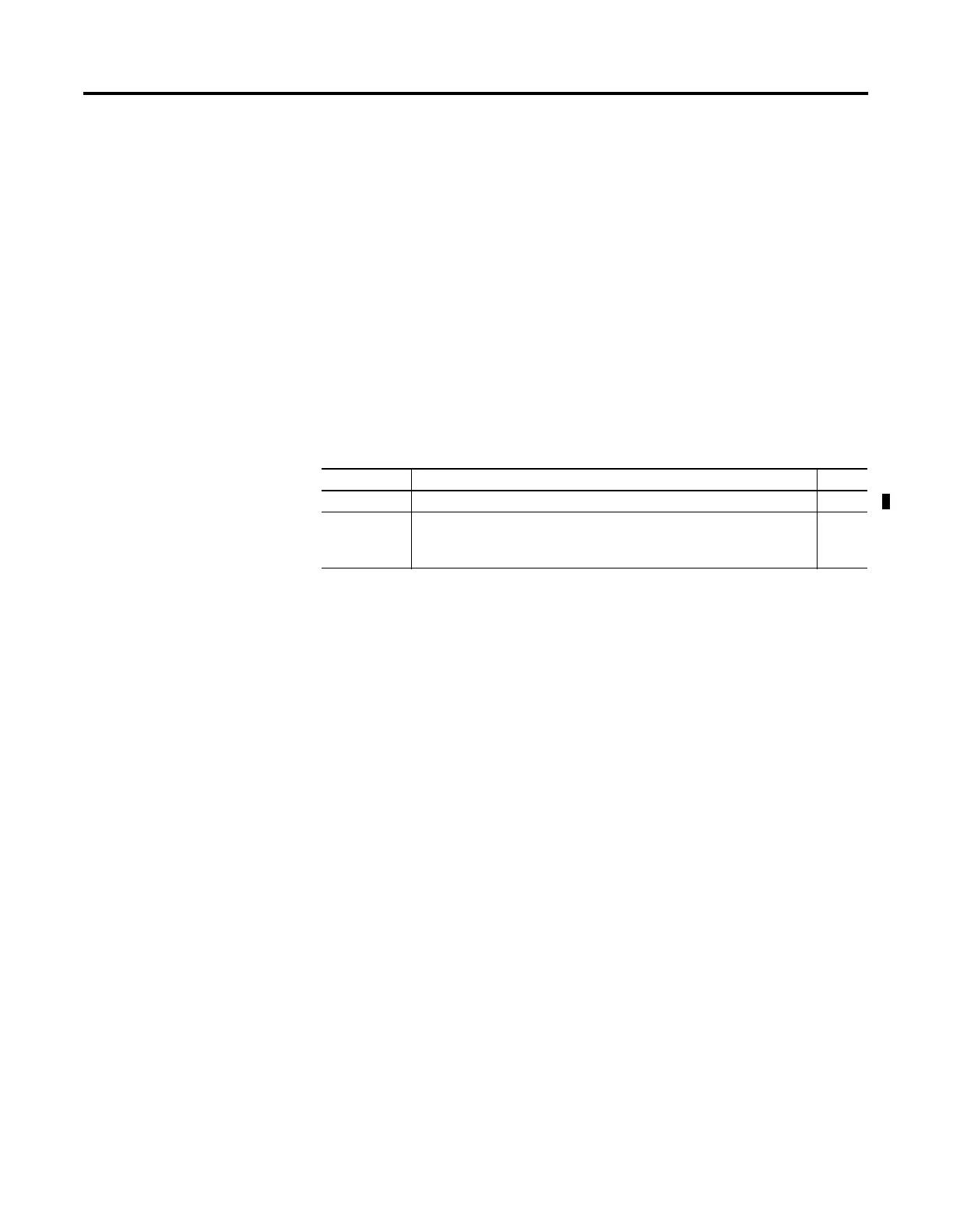
Instruction Used To: Page
MSG Transfer data from one device to another. 21-3
SVC Interrupt the program scan to execute the service communications part
of the operating cycle. The scan then resumes at the instruction
following the SVC instruction.
21-26

 Loading...


