Publication 1762-RM001C-EN-P
21-12 Communications Instructions
Channel
This variable defines the communication channel that is used to transmit
the message request. For controllers with only one communication
channel, this value is factory-set to channel 0 and cannot be changed. For
controllers with 2 channels (1764-LRP processor installed), the channel
can be 0 or 1.
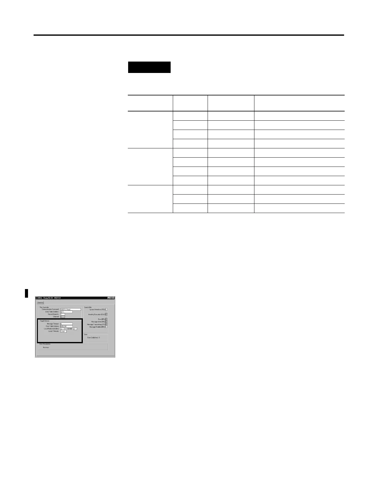
“Target Device” Parameters
Message Timeout
This value defines how long, in seconds, the message instruction has to
complete its operation once it has started. Timing begins when the
false-to-true rung transition occurs, enabling the message. If the timeout
period expires, the message errors out. The default value is 5 seconds.
The maximum timeout value is 255 seconds.
If the message timeout is set to zero, the message instruction will never
timeout. Set the Time Out bit (TO = 1) to flush a message instruction from
its buffer if the destination device does not respond to the
communications request.
NOTE
The table below is not intended to illustrate file
compatibility, only the maximum number of elements that
can be exchanged in each case.
Message Type File Type Element Size Maximum Number
of Elements per Message
485CIF O, I, B, N 1-word 103
L2-word51
T, C, R 3-word 34
ST 42-word 2 (write only)
500CPU O, I, B, N 1-word 103
L2-word51
T, C, R 3-word 34
RTC 8-word 1 (write only)
PLC5 O, I, B, N 1-word 103
L2-word51
T5-word20

 Loading...


