Publication 1762-RM001C-EN-P
Communications Instructions 21-19
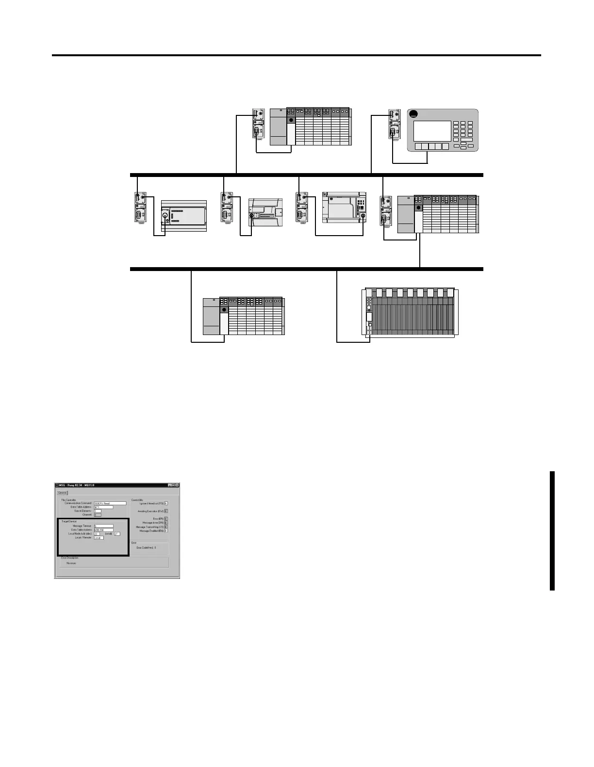
Figure 21.3 DH-485 and DH+ Example Network
“This Controller” Parameters
See “Target Device” Parameters on page 21-12.
“Control Bits” Parameters
See “Control Bits” Parameters on page 21-14.
“Target Device” Parameters
Message Timeout
See Message Timeout on page 21-12.
Data Table Address
See Data Table Address/Offset on page 21-13.
Local Bridge Address
This variable defines the bridge address on the local network. In the
example, DH-485 node 12 (MicroLogix 1500 on Link ID 1) is writing data
to node 51 (SLC 5/04 on Link ID 100). The SLC 5/04 at node 17 is the
bridge device.
This variable sends the message to local node 17.
A-B
PanelView
TERM
A
B
COM
SHLD
CHS GND
TX
TX PWR
TX
DC SOURCE
CABLE
EXTERNAL
TERM
A
B
COM
SHLD
CHS GND
TX
TX PWR
TX
DC SOURCE
CABLE
EXTERNAL
TERM
A
B
COM
SHLD
CHS GND
TX
TX PWR
TX
DC SOURCE
CABLE
EXTERNAL
TERM
A
B
COM
SHLD
CHS GND
TX
TX PWR
TX
DC SOURCE
CABLE
EXTERNAL
TERM
A
B
COM
SHLD
CHS GND
TX
TX PWR
TX
DC SOURCE
CABLE
EXTERNAL
TERM
A
B
COM
SHLD
CHS GND
TX
TX PWR
TX
DC SOURCE
CABLE
EXTERNAL
AIC+ AIC+ AIC+
AIC+
DH-485 Network
SLC 5/03
PanelView 550
MicroLogix 1500MicroLogix 1000 MicroLogix 1200
SLC 5/04
AIC+
AIC+
SLC 5/04 PLC-5
DH+ Network
Node 17
Node 23 octal (19 decimal)
Node 63 octal (51 decimal) Node 40 octal (32 decimal)
Node 12
Node 5 Node 22
Node 11Node 10
Link ID = 100
Link ID = 1

 Loading...


