Publication 1762-RM001C-EN-P
Function Files 3-11
Target Bit File (TBF)
The value stored in the TBF location identifies the bit file with which the
DAT will interface. The DAT can read or write to any valid bit file within
the controller. Valid bit files are B3 through B255. When the DAT reads a
valid bit file number, it can access the first 48 bits (0 to 47) of the specified
file on its display screen. The next 48 bits (48 to 95) are used to define the
read-only or read/write privileges for the first 48 bits.
The only bit file that the DAT interfaces with is the file specified in the
TBF location. The TBF location can only be changed by a program
download.
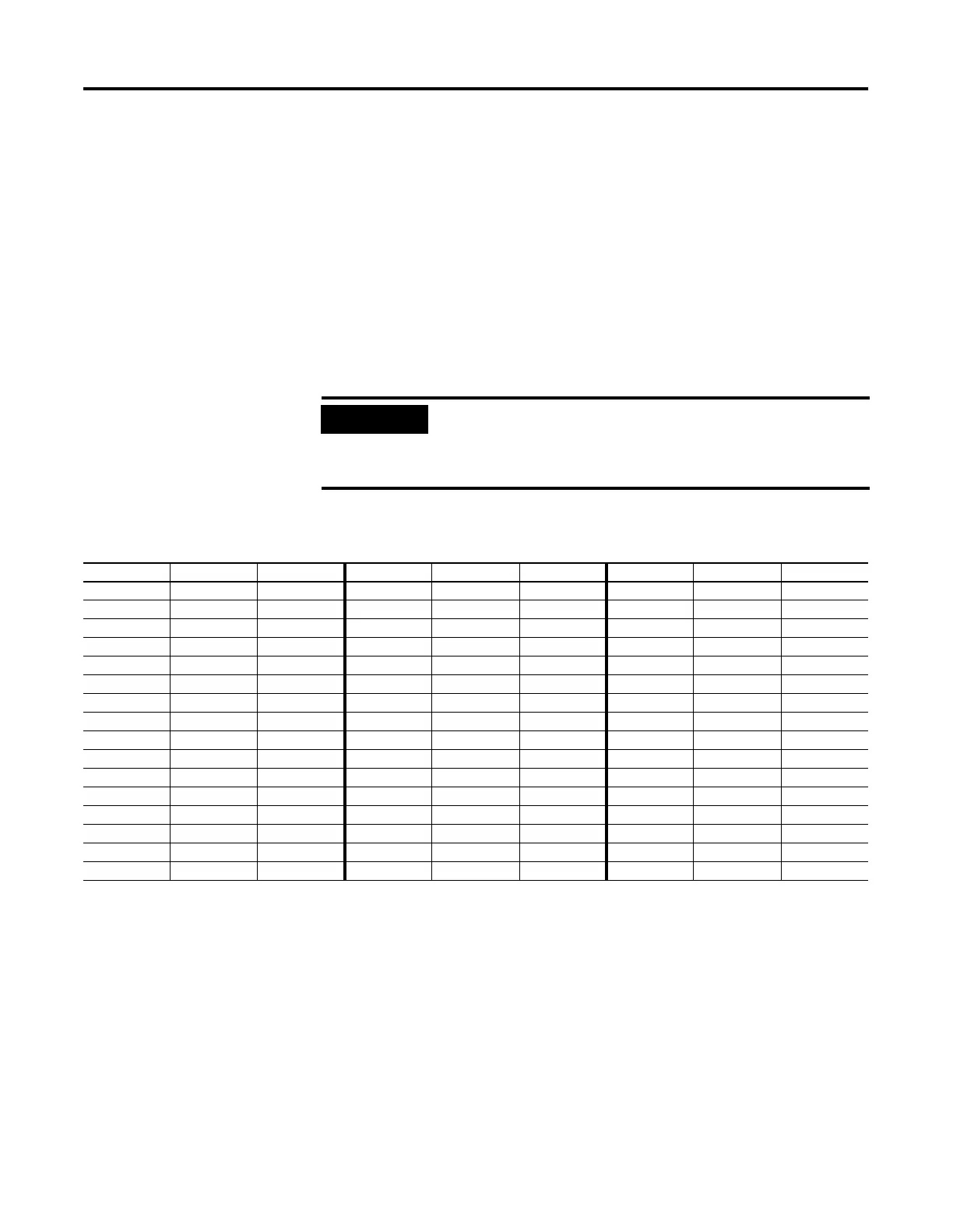
The example table below shows how the DAT uses the configuration
information with bit file number 51 (DAT:0.TBF=51).
The bit number displayed on the DAT corresponds to the data bit as
illustrated in the table. The protection bit defines whether the data is
editable or read-only. When the protection bit is set (1), the
corresponding data address is considered read-only by the DAT. The
Protected LED illuminates whenever a read-only element is active on the
DAT display. When the protection bit is clear (0) or the protection bit
does not exist, the Protected LED is off and the data within the
corresponding address is editable from the DAT keypad.
IMPORTANT
Use your programming software to ensure that the bit file
you specify in the TBF location, as well as the appropriate
number of elements, exist in the MicroLogix 1500 user
program.
Bit Number Data Address Protection Bit Bit Number Data Address Protection Bit Bit Number Data Address Protection Bit
0 B51/0 B51/48 16 B51/16 B51/64 32 B51/32 B51/80
1 B51/1 B51/49 17 B51/17 B51/65 33 B51/33 B51/81
2 B51/2 B51/50 18 B51/18 B51/66 34 B51/34 B51/82
3 B51/3 B51/51 19 B51/19 B51/67 35 B51/35 B51/83
4 B51/4 B51/52 20 B51/20 B51/68 36 B51/36 B51/84
5 B51/5 B51/53 21 B51/21 B51/69 37 B51/37 B51/85
6 B51/6 B51/54 22 B51/22 B51/70 38 B51/38 B51/86
7 B51/7 B51/55 23 B51/23 B51/71 39 B51/39 B51/87
8 B51/8 B51/56 24 B51/24 B51/72 40 B51/40 B51/88
9 B51/9 B51/57 25 B51/25 B51/73 41 B51/41 B51/89
10 B51/10 B51/58 26 B51/26 B51/74 42 B51/42 B51/90
11 B51/11 B51/59 27 B51/27 B51/75 43 B51/43 B51/91
12 B51/12 B51/60 28 B51/28 B51/76 44 B51/44 B51/92
13 B51/13 B51/61 29 B51/29 B51/77 45 B51/45 B51/93
14 B51/14 B51/62 30 B51/30 B51/78 46 B51/46 B51/94
15 B51/15 B51/63 31 B51/31 B51/79 47 B51/47 B51/95

 Loading...


