Publication 1762-RM001C-EN-P
3-10 Function Files
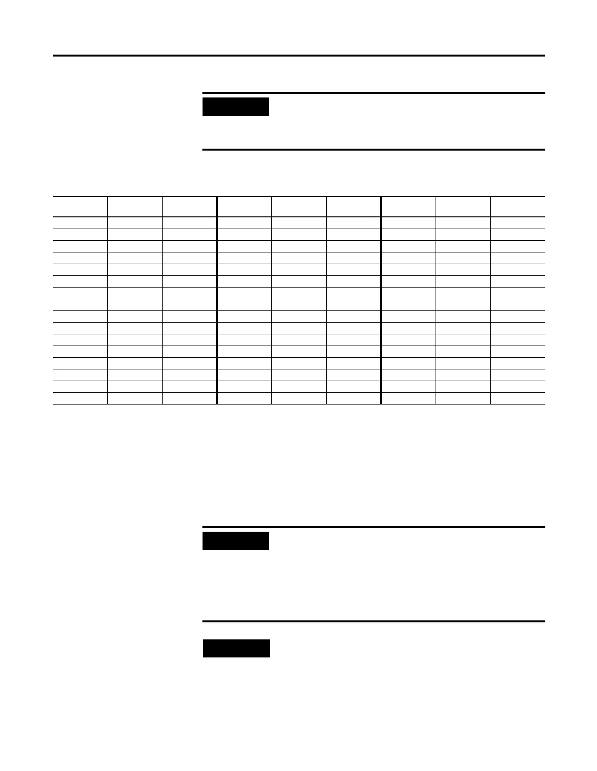
The example table below shows a DAT configured to use integer file
number 50 (DAT:0.TIF = 50).
The element number displayed on the DAT corresponds to the data
register as illustrated in the table. The protection bit defines whether the
data is read/write or read-only. When the protection bit is set (1), the
corresponding data address is considered read-only by the DAT. The
Protected LED illuminates whenever a read-only element is active on the
DAT display. When the protection bit is clear (0) or the protection bit
does not exist, the Protected LED is off and the data within the
corresponding address is editable from the DAT keypad.
IMPORTANT
Use your programming software to ensure that the integer
file you specify in the TIF location, as well as the
appropriate number of elements, exist in the controller’s
user program.
Element
Number
Data Address Protection Bit Element
Number
Data Address Protection Bit Element
Number
Data Address Protection Bit
0 N50:0 N50:48/0 16 N50:16 N50:49/0 32 N50:32 N50:50/0
1 N50:1 N50:48/1 17 N50:17 N50:49/1 33 N50:33 N50:50/1
2 N50:2 N50:48/2 18 N50:18 N50:49/2 34 N50:34 N50:50/2
3 N50:3 N50:48/3 19 N50:19 N50:49/3 35 N50:35 N50:50/3
4 N50:4 N50:48/4 20 N50:20 N50:49/4 36 N50:36 N50:50/4
5 N50:5 N50:48/5 21 N50:21 N50:49/5 37 N50:37 N50:50/5
6 N50:6 N50:48/6 22 N50:22 N50:49/6 38 N50:38 N50:50/6
7 N50:7 N50:48/7 23 N50:23 N50:49/7 39 N50:39 N50:50/7
8 N50:8 N50:48/8 24 N50:24 N50:49/8 40 N50:40 N50:50/8
9 N50:9 N50:48/9 25 N50:25 N50:49/9 41 N50:41 N50:50/9
10 N50:10 N50:48/10 26 N50:26 N50:49/10 42 N50:42 N50:50/10
11 N50:11 N50:48/11 27 N50:27 N50:49/11 43 N50:43 N50:50/11
12 N50:12 N50:48/12 28 N50:28 N50:49/12 44 N50:44 N50:50/12
13 N50:13 N50:48/13 29 N50:29 N50:49/13 45 N50:45 N50:50/13
14 N50:14 N50:48/14 30 N50:30 N50:49/14 46 N50:46 N50:50/14
15 N50:15 N50:48/15 31 N50:31 N50:49/15 47 N50:47 N50:50/15
IMPORTANT
Although the DAT does not allow protected data to be
changed from its keypad, the control program or other
communication devices do have access to this data.
Protection bits do not provide any overwrite protection to
data within the target integer file. It is entirely the user’s
responsibility to ensure that data is not inadvertently
overwritten.
NOTE
•
Remaining addresses within the target file can be used
without restrictions (addresses N50:51 and above, in
this example).
•
The DAT always starts at word 0 of a data file. It cannot
start at any other address within the file.

 Loading...


