Publication 1762-RM001C-EN-P
Using the High-Speed Counter 5-9
User Interrupt Pending (UIP)
The UIP (User Interrupt Pending) is a status flag that represents an
interrupt is pending. This status bit can be monitored or used for logic
purposes in the control program if you need to determine when a
subroutine cannot be executed immediately.
This bit is maintained by the controller and is set and cleared
automatically.
User Interrupt Lost (UIL)
The UIL (User Interrupt Lost) is a status flag that represents an interrupt
has been lost. The controller can process 1 active and maintain up to 2
pending user interrupt conditions.
This bit is set by the controller. It is up to the control program to utilize,
track if necessary, and clear the lost condition.
Low Preset Mask (LPM)
The LPM (Low Preset Mask) control bit is used to enable (allow) or
disable (not allow) a low preset interrupt from occurring. If this bit is clear
(0), and a Low Preset Reached condition is detected by the HSC, the HSC
user interrupt is not executed.
This bit is controlled by the user program and retains its value through a
power cycle. It is up to the user program to set and clear this bit.
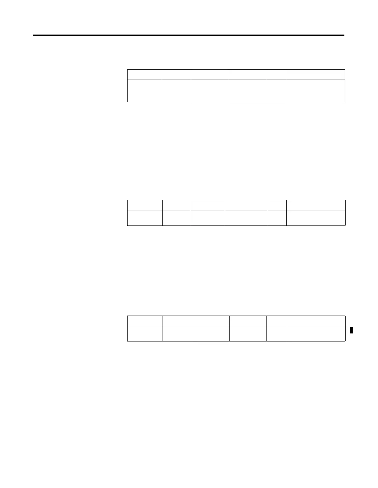
Description Address Data Format
HSC Modes
(1)
(1) For Mode descriptions, see HSC Mode (MOD) on page 5-16.
Type User Program Access
UIP - User
Interrupt
Pending
HSC:0/UIP bit 0 to 7 status read only
Description Address Data Format
HSC Modes
(1)
(1) For Mode descriptions, see HSC Mode (MOD) on page 5-16.
Type User Program Access
UIL - User
Interrupt Lost
HSC:0/UIL bit 0 to 7 status read/write
Description Address Data Format
HSC Modes
(1)
(1) For Mode descriptions, see HSC Mode (MOD) on page 5-16.
Type User Program Access
LPM - Low
Preset Mask
HSC:0/LPM bit 2 to 7 control read/write

 Loading...


