14 MicroLogix™ Analog Input/Output Module
Publication 1762-IN005A-US-P
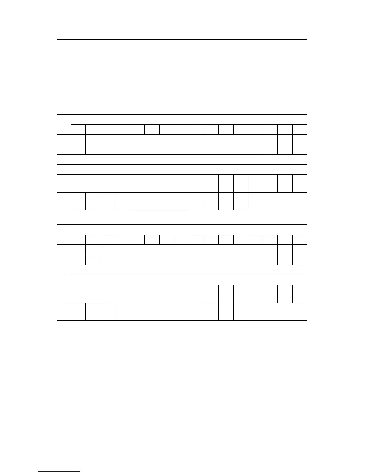
Input Data File
For each module, slot x, words 0 and 1 contain the analog values of the inputs.
The module can be configured to use either raw/proportional data or
scaled-for-PID data. The input data file for each configuration is shown below.
The bits are defined as follows:
• SIx = General status bits for input channels 0 and 1.
SOx = General status bits for output channels 0 and 1. This bit is set when an
error (over- or under-range) exists for that channel, or there is a general
module hardware error.
• OIx = Over-range flag bits for input channels 0 and 1.
OOx = Over-range flag bits for output channels 0 and 1. These bits can be used
in the control program for error detection.
• UIx = Under-range flag bits for input channels 0 and 1.
UOx = Under-range flag bits for output channels 0 and 1. These bits can be
used in the control program for error detection.
Raw/Proportional Format
Word
Bit Position
1514131211109876543210
0 0 Channel 0 Data 0 to 32760 0 0 0
1 0 Channel 1 Data 0 to 32760 0 0 0
2 reserved
3 reserved
4
reserved
SO
1
SO
0
reserved
SI
1
SI
0
5UI
0
OI
0
UI
1
OI
1
reserved
UO
0
OO
0
UO
1
OO
1
reserved
Scaled-for-PID Format
Word
Bit Position
1514131211109876543210
0 0 0 Channel 0 Data 0 to 16,380 0 0
1 0 0 Channel 1 Data 0 to 16,380 0 0
2 reserved
3 reserved
4
reserved
SO
1
SO
0
reserved
SI
1
SI
0
5UI
0
OI
0
UI
1
OI
1
reserved
U0
0
O0
0
U0
1
O0
1
reserved

 Loading...


