MicroLogix™ Analog Input/Output Module 9
Publication 1762-IN005A-US-P
Wiring
System Wiring Guidelines
Consider the following when wiring your system:
• The analog common (COM) is not connected to earth ground inside the
module. All terminals are electrically isolated from the system.
• Channels are not isolated from each other.
• Use Belden™ 8761, or equivalent, shielded wire.
• Under normal conditions, the drain wire (shield) should be connected to the
metal mounting panel (earth ground). Keep shield connection to earth ground
as short as possible.
• To ensure optimum accuracy for voltage type inputs and outputs, limit overall
cable impedance by keeping all analog cables as short as possible. Locate the
I/O system as close to your voltage type sensors or actuators as possible.
• The 1762-IF2OF2 module does not provide loop power for analog inputs. Use
a power supply that matches the input transmitter specifications.
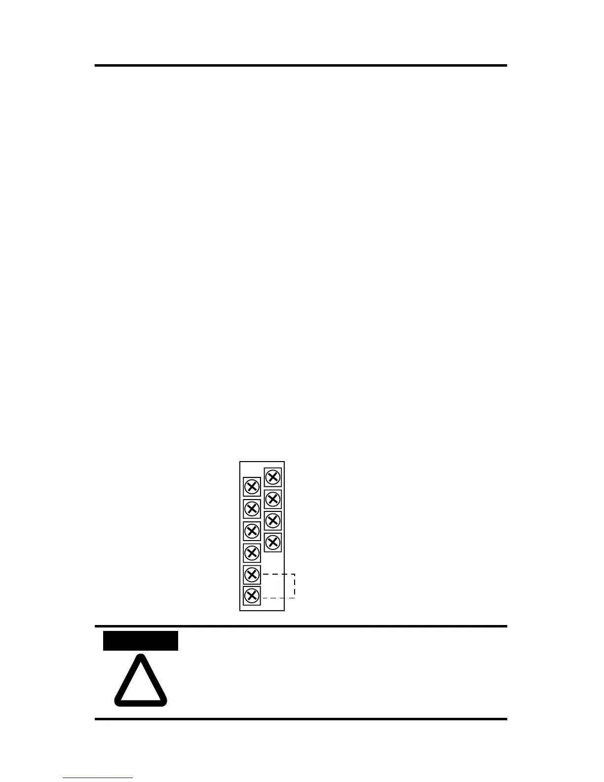
Terminal Block Layout
!
ATTENTION
Analog outputs may fluctuate for less than a second when
power is applied or removed. This characteristic is common to
most analog outputs. While the majority of loads will not
recognize this short signal, it is recommended that preventive
measures be taken to ensure that connected equipment is not
affected.
V out 1
V out 0
IN 1 +
IN 0 +
I out 1
I out 0
IN 1 -
IN 0 -
COM
COM
Commons connected
internally.
Allen-Bradley HMIs

 Loading...


