MicroLogix™ Analog Input/Output Module 5
Publication 1762-IN005A-US-P
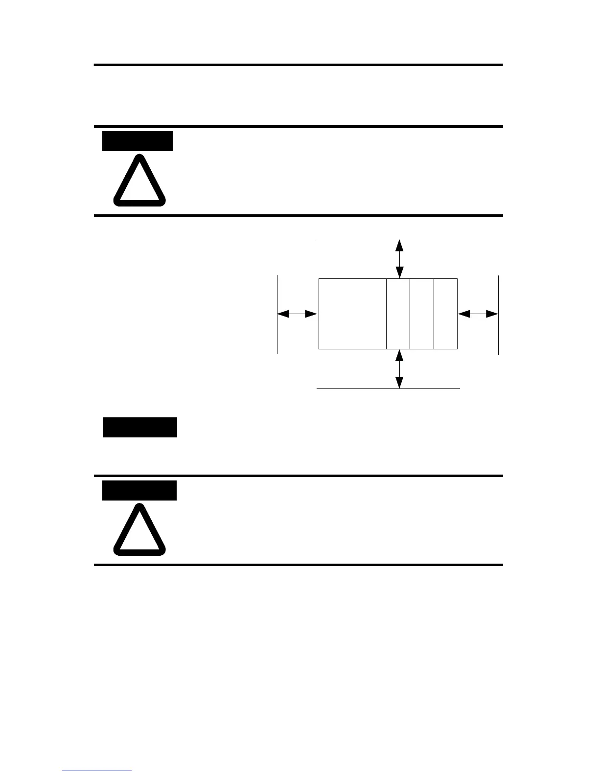
Mounting
Minimum Spacing
Maintain spacing from
enclosure walls, wireways,
adjacent equipment, etc.
Allow 50.8 mm (2 in.) of
space on all sides for
adequate ventilation, as
shown:
!
ATTENTION
Do not remove protective debris strip until after the module and
all other equipment near the module is mounted and wiring is
complete. Once wiring is complete and the module is free of
debris, carefully remove protective debris strip. Failure to
remove strip before operating can cause overheating.
NOTE
1762 expansion I/O may be mounted horizontally only.
!
ATTENTION
During panel or DIN rail mounting of all devices, be sure that
all debris (metal chips, wire strands, etc.) is kept from falling
into the module. Debris that falls into the module could cause
damage when power is applied to the module.
MicroLogix
1200
1762 I/O
1762 I/O
1762 I/O
Side
Side
Top
Bottom
Allen-Bradley HMIs
 Loading...


