6 MicroLogix™ Analog Input/Output Module
Publication 1762-IN005A-US-P
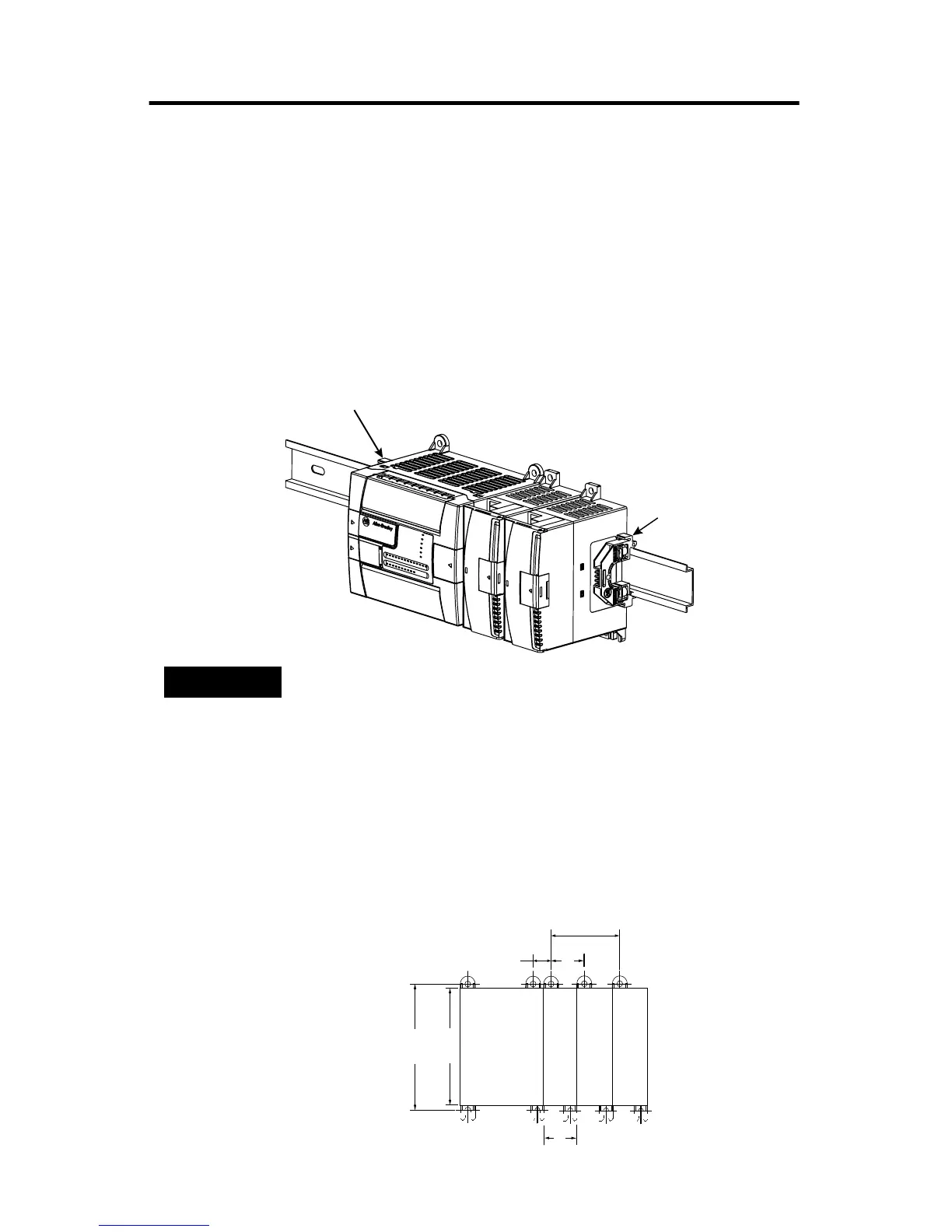
DIN Rail Mounting
The module can be mounted using the following DIN rails: 35 x 7.5 mm
(EN 50 022 - 35 x 7.5) or 35 x 15 mm (EN 50 022 - 35 x 15).
Before mounting the module on a DIN rail, close the DIN rail latch. Press the
DIN rail mounting area of the module against the DIN rail. The latch will
momentarily open and lock into place.
Use DIN rail end anchors (Allen-Bradley part number 1492-EA35 or
1492-EAH35) for environments with vibration or shock concerns.
Panel Mounting
Use the dimensional template shown below to mount the module. The preferred
mounting method is to use two M4 or #8 panhead screws per module. M3.5 or #6
panhead screws may also be used, but a washer may be needed to ensure a good
ground contact. Mounting screws are required on every module.
NOTE
For environments with extreme vibration and shock concerns,
use the panel mounting method described below, instead of
DIN rail mounting.
End Anchor
End Anchor
90
(3.54)
100
(3.94)
40.4
(1.59)
40.4
(1.59)
14.5
(0.57)
For more than 2 modules: (number of modules - 1) x 40.4 mm (1.59 in.)
NOTE:
Hole spacing tolerance:
±0.4 mm (0.016 in.).
MicroLogix 1200
Expansion I/O
MicroLogix 1200
Expansion I/O
MicroLogix 1200
Expansion I/O
MicroLogix 1200

 Loading...


