102 Rockwell Automation Publication 2711P-UM006A-EN-P - November 2010
Chapter 6 Install and Replace Components
Install or Replace the Logic
Module
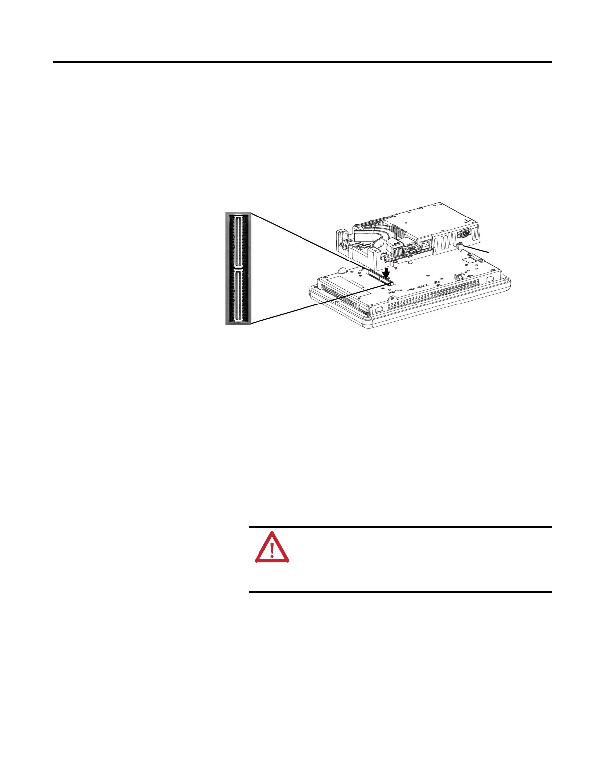
If the display module and logic module are ordered as separate components,
attach the logic module to the display module before panel installation.
1. Make sure power is disconnected power from the terminal.
2. Set the display module display-side down on a clean, flat, stable surface.
3. Position the logic over the back of the display module, aligning the logic
module connector with the connectors on the display module.
4. Push down on the logic module until it is firmly seated.
5. Tighten the four captive screws that secure the logic module to the display
module and torque to 0.58 N•m (5…7 lb•in).
Before replacing a logic module, you must first remove the communication
module, if attached.
Follow these steps to replace a logic module.
1. Disconnect power from the terminal.
2. Disconnect all power and communication cables.
3. Set the display module display-side down on a clean, flat, stable surface.
WARNING: Do not connect or disconnect any communication
cable with power applied to this device or any device on a
network. An electrical arc could cause an explosion in hazardous
location installations. Be sure power is removed or the area is
known to be nonhazardous before proceeding.
Captive
Screw

 Loading...


