212 Rockwell Automation Publication 750-IN001O-EN-P - October 2014
Chapter 4 Power Wiring
Wall Mount Frames 2…5 Power Jumper Screw Removal and Storage
Wall/Flange Mount Frames 2…5 use jumper screws to complete an electrical
connection when installed. Install or remove jumper screws according to the
recommendations in Ta b le 29
.
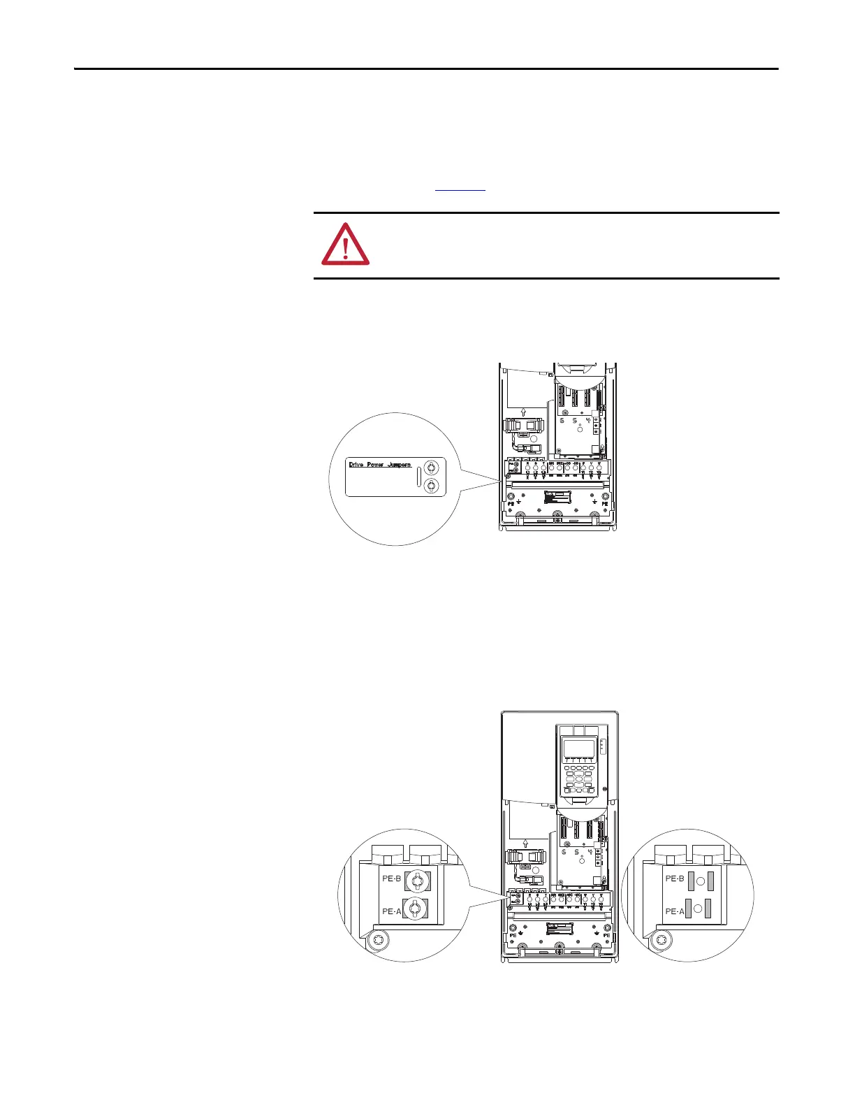
When power jumper screws are not used, they are stored on the left interior
chassis wall as shown.
Figure 114 - Typical Wall Mount Frames 2…5 Jumper Screw Storage Location (Frame 4 shown)
When screws are installed:
• Recommended torque = 1.36 N•m (12.0 lb•in) +/- 0.14 N•m (1.2 lb•in)
• Recommended screwdriver = 6.4 mm (0.25 in.) flat or
T15 Hexalobular
Figure 115 - Typical Wall Mount Frames 2…5 Jumper Screw Installation Locations (Frame 4
shown)
ATTENTION: Hazard of equipment damage exists if jumpers are not properly
disconnected. For Frames 2…5, completely remove the jumper screw from the
circuit board.
 Loading...


