Rockwell Automation Publication 750-IN001O-EN-P - October 2014 213
Power Wiring Chapter 4
Wall Mount Frames 1, 6, and 7 Power Jumper Wire Removal and
Storage
Wall/Flange Mount Frames 1, 6, and 7 use jumper wires to complete an electrical
connection when installed. Install or remove jumper wires according to the
recommendations in Ta b le 29
.
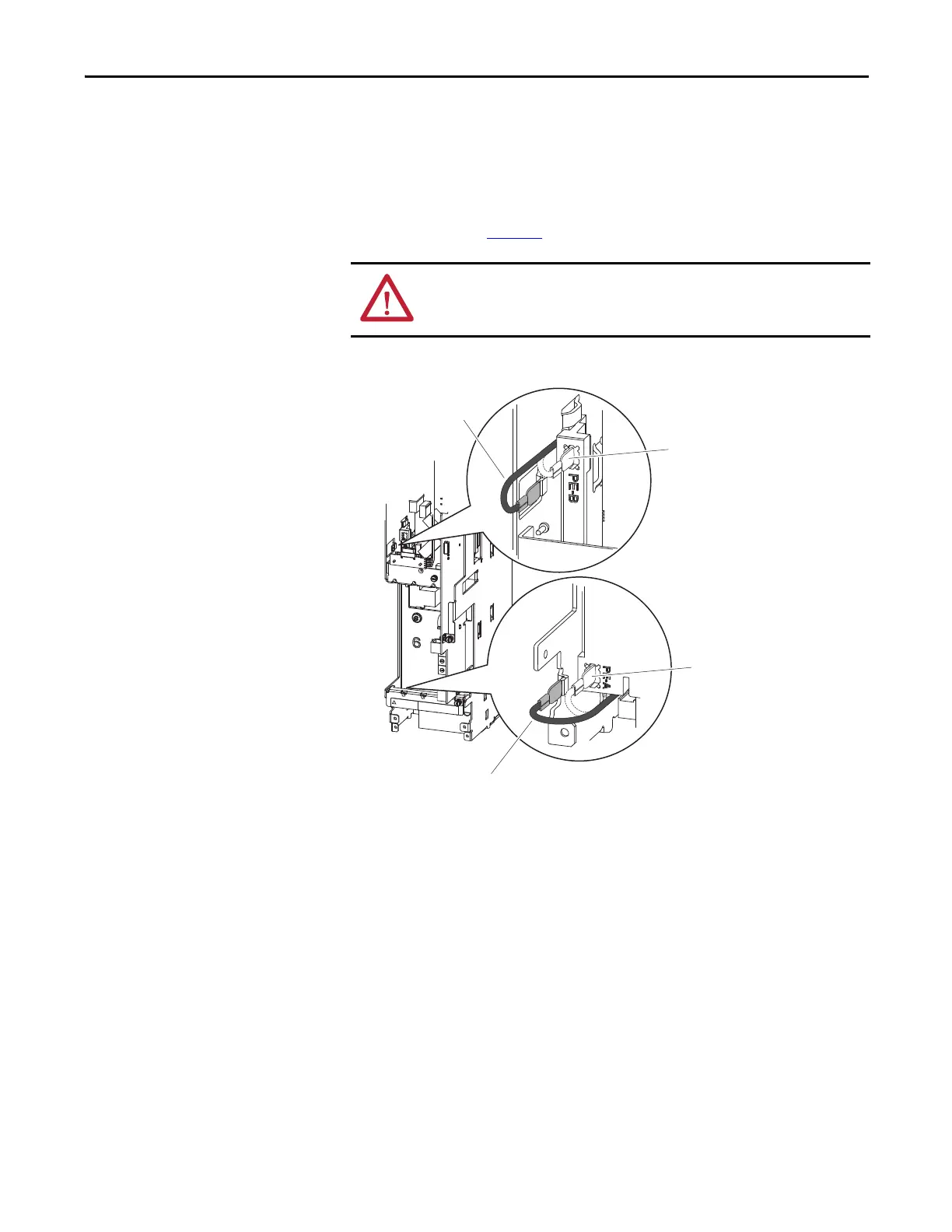
Figure 116 - Wall Mount Frame 1 Jumper Wire Locations
When jumper wires are connected, the spade connector should be pressed firmly
onto the sheet metal tab.
ATTENTION: Hazard of equipment damage exists if jumpers are not properly
disconnected. For Frames 1, 6, and 7, secure the disconnected jumper wire to
the insulated position provided.
PE-A
PE-B
Disconnected
Connected
Disconnected
Connected
 Loading...


