EasyManuals Logo
Home>Allen-Bradley>Controller>PowerFlex 4

Allen-Bradley PowerFlex 4 User Manual

Allen-Bradley PowerFlex 4
108 pages
To Next Page IconTo Next Page
To Previous Page IconTo Previous Page
Page #85 background imageLoading...
Page #85 background image
Accessories and Dimensions B-9
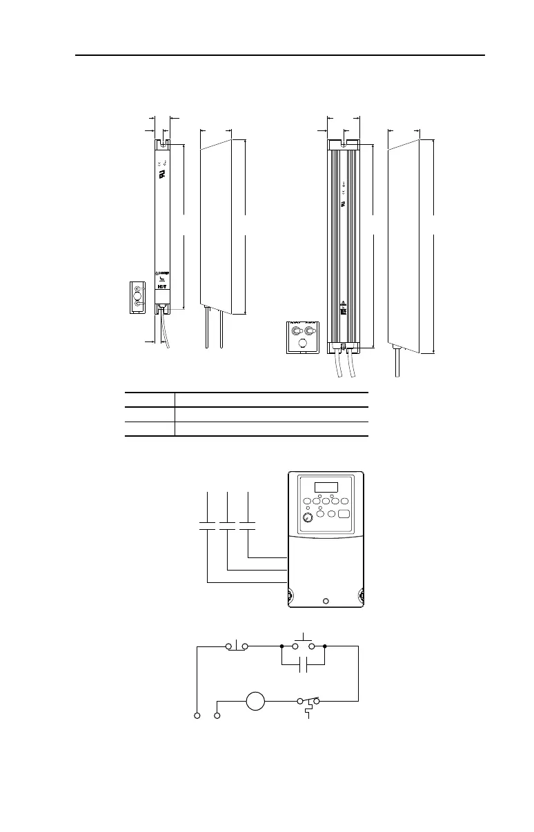
Figure B.6 Dynamic Brake Modules – Dimensions are in millimeters and (inches)
Figure B.7 Recommended External Brake Resistor Circuitry
Frame Catalog Number
A AK-R2-091P500, AK-R2-047P500, AK-R2-360P500
B AK-R2-030P1K2, AK-R2-120P1K2
335.0
(13.19)
60.0
(2.36)
30.0
(1.18)
17.0
(0.67)
59.0
(2.32)
13.0
(0.51)
405.0
(15.94)
386.0
(15.20)
316.0
(12.44)
61.0
(2.40)
31.0
(1.22)
ROCKWELL
AUTOMATION
CUS
SURFACES MAY BE
ROCKWELL
AUTOMATION
CUS
Frame A Frame B
Power On
R (L1)
S (L2)
T (L3)
Power Source DB Resistor Thermostat
Power Off
M
M
(Input Contactor) M
Three-Phase
AC Input

Table of Contents

Other manuals for Allen-Bradley PowerFlex 4

Questions and Answers:

Question and Answer IconNeed help?

Do you have a question about the Allen-Bradley PowerFlex 4 and is the answer not in the manual?

Allen-Bradley PowerFlex 4 Specifications

General IconGeneral
BrandAllen-Bradley
ModelPowerFlex 4
CategoryController
LanguageEnglish

Related product manuals