Rockwell Automation Publication 520-UM001A-EN-E - February 2013 185
Velocity StepLogic, Basic Logic and Timer/Counter Functions Appendix D
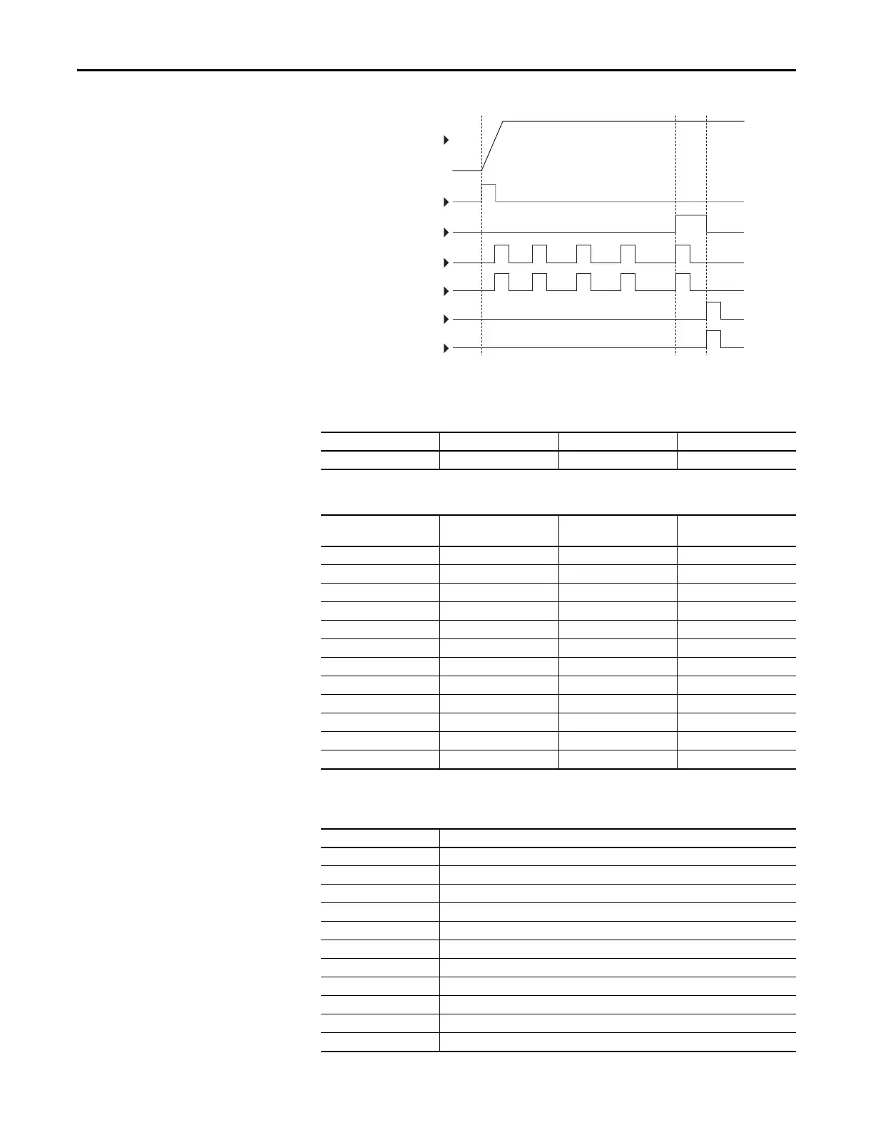
Velocity StepLogic
Parameters
DigIn TermBlk 06
Reset Counter
Limit Switch
DigIn TermBlk 05
Counter In
Photo Eye
Start
Output
Frequency
Relay Out
Code Descriptions for Parameters L180...L187
Digit 4 Digit 3 Digit 2 Digit 1
00F1
Digit 4 – Defines the action during the step currently executing
Setting Accel/Decel Parameter
Used
StepLogic Output State Commanded Direction
01OffFWD
11OffREV
21OffNo Output
31OnFWD
41OnREV
5 1 On No Output
62OffFWD
72OffREV
82OffNo Output
92OnFWD
A2OnREV
b 2 On No Output
Digit 3 – Defines what step to jump to or how to end program when the logic conditions specified
in Digit 2 are met.
Setting Logic
0Jump to Step 0
1Jump to Step 1
2Jump to Step 2
3Jump to Step 3
4Jump to Step 4
5Jump to Step 5
6Jump to Step 6
7Jump to Step 7
8 End Program (Normal Stop)
9 End Program (Coast to Stop)
A End Program and Fault (F002)
 Loading...


