Rockwell Automation Publication 520-UM001A-EN-E - February 2013 199
Appendix F
PID Set Up
PID Loop
The PowerFlex 525 drive has two built-in PID (proportional, integral, derivative)
control loops, of which only one can be in use at any time. The PID loop is used
to maintain a process feedback (such as pressure, flow or tension) at a desired set
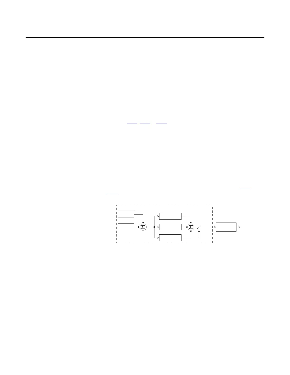
point. The PID loop works by subtracting the PID feedback from a reference and
generating an error value. The PID loop reacts to the error, based on the PID
Gains, and outputs a frequency to try to reduce the error value to 0. To enable the
PID loop, P047
, P049 or P051 [Speed Referencex] must be set to 11 “PID1
Output” or 12 “PID2 Output”, and the corresponding speed reference activated.
Exclusive Control and Trim Control are two basic configurations where the PID
loop may be used.
Exclusive Control
In Exclusive Control, the Speed Reference becomes 0, and the PID Output
becomes the entire Freq Command. Exclusive Control is used when A458
or
A470
[PID x Trim Sel] is set to option 0. This configuration does not require a
master reference, only a desired set point, such as a flow rate for a pump.
Example
• In a pumping application, the PID Reference equals the Desired System
Pressure set point.
• The Pressure Transducer signal provides PID Feedback to the drive.
Fluctuations in actual system pressure, due to changes in flow, result in a
PID Error value.
• The drive output frequency increases or decreases to vary motor shaft
speed to correct for the PID Error value.
• The Desired System Pressure set point is maintained as valves in the system
are opened and closed causing changes in flow.
–
+
PID Prop Gain
PID Loop
PID Integ Time
PID Di Rate
PID Selected
PID Fdbk
PID Ref
PID
Error
+
+
+
PID
Output
Accel/Decel
Ramp
Freq
Command

 Loading...


