EasyManuals Logo

Allen-Bradley PowerFlex 525 User Manual

Allen-Bradley PowerFlex 525
228 pages
To Next Page IconTo Next Page
To Previous Page IconTo Previous Page
Page #25 background imageLoading...
Page #25 background image
Rockwell Automation Publication 520-UM001A-EN-E - February 2013 25
Installation/Wiring Chapter 1
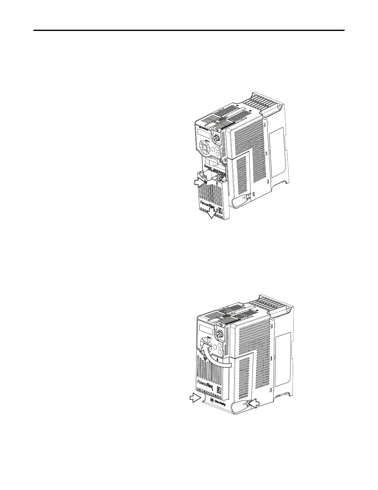
Control Module Cover
To access the control terminals, DSI port, and Ethernet port, the front cover must
be removed. To remove:
1. Press and hold down the arrow on the front of the cover.
2. Slide the front cover down to remove from the Control Module.
Re-attach the front cover when wiring is complete.
Power Module Terminal
Guard
To access the power terminals, the terminal guard must be removed. To remove:
1. Press and hold down the catch on both sides of the frame cover, then pull
out and swing upwards to remove. (Frames B...E only)
1
2

Table of Contents

Other manuals for Allen-Bradley PowerFlex 525

Questions and Answers:

Question and Answer IconNeed help?

Do you have a question about the Allen-Bradley PowerFlex 525 and is the answer not in the manual?

Allen-Bradley PowerFlex 525 Specifications

General IconGeneral
Horsepower0.5-30 HP
kW0.4-22 kW
Input Voltage200-240V AC, 380-480V AC
EnclosureIP20, NEMA/UL Type 1
CommunicationsEtherNet/IP
Control MethodsV/Hz, Sensorless Vector
STOSafe Torque Off (STO)
Output Voltage0-Input Voltage
Operating Temperature-20°C to 50°C (-4°F to 122°F)
Storage Temperature-40°C to 85°C (-40°F to 185°F)
Relative Humidity5-95% non-condensing
DimensionsVaries by model
WeightVaries by model

Related product manuals