Rockwell Automation Publication 520-UM001A-EN-E - February 2013 31
Installation/Wiring Chapter 1
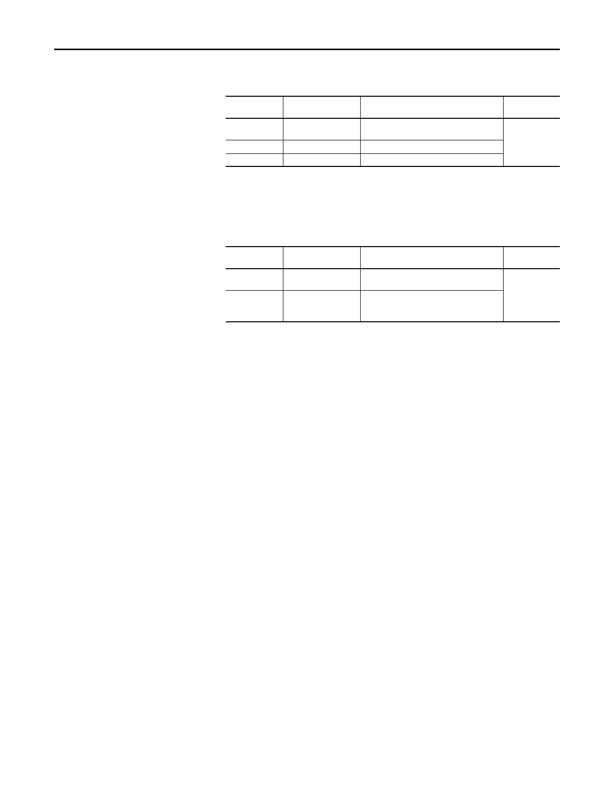
Maximum Control Wire Recommendations
Do not exceed control wiring length of 30 m (100 ft). Control signal cable length
is highly dependent on electrical environment and installation practices. To
improve noise immunity, the I/O terminal block Common may be connected to
ground terminal/protective earth. If using the RS485 (DSI) port, I/O Terminal
C1 should also be connected to ground terminal/protective earth. Additionally,
communication noise immunity can also be improved by connecting I/O
Terminal C2 to ground terminal/protective earth.
Recommended Signal Wire
Signal Type/
Where Used
Belden Wire Type(s)
(1)
(or equivalent)
(1) Stranded or solid wire.
Description Min. Insulation
Rating
Analog I/O & PTC 8760/9460 0.750 mm
2
(18 AWG), twisted pair,
100% shield with drain
(2)
(2) If the wires are short and contained within a cabinet which has no sensitive circuits, the use of shielded wire may not be necessary,
but is always recommended.
300V,
60 °C (140 °F)
Remote Pot 8770 0.750 mm
2
(18 AWG), 3 conductor, shielded
Encoder/Pulse I/O 9728/9730 0.196 mm
2
(24 AWG), individually shielded pairs
Recommended Control Wire for Digital I/O
Type Wire Type(s) Description Min. Insulation
Rating
Unshielded Per US NEC or applicable
national or local code
– 300V,
60 °C (140 °F)
Shielded Multi-conductor shielded
cable such as Belden 8770
(or equivalent)
0.750 mm
2
(18 AWG), 3 conductor, shielded.

 Loading...


