Rockwell Automation Publication 20A-UM001N-EN-P - July 2013 39
Programming and Parameters Chapter 1
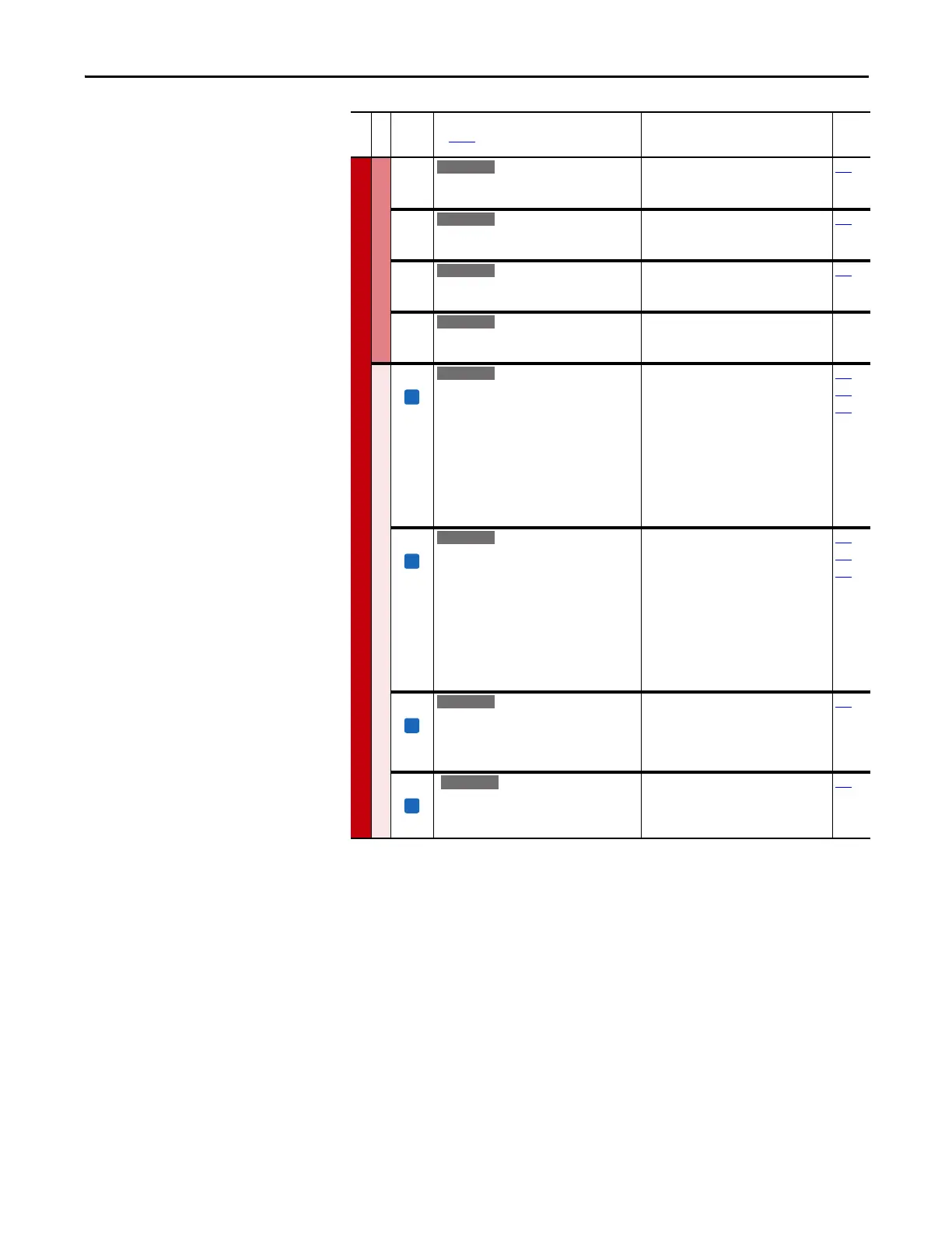
SPEED COMMAND (file C)
Process PI
460 [PI Reference Hi]
Scales the upper value of [PI Reference Sel] of
the source.
Default:
Min/Max:
Units:
100.0%
±100.0%
0.1%
126
461 [PI Reference Lo]
Scales the lower value of [PI Reference Sel]
of the source.
Default:
Min/Max:
Units:
–100.0%
±100.0%
0.1%
126
462 [PI Feedback Hi]
Scales the upper value of [PI Feedback] of
the source.
Default:
Min/Max:
Units:
100.0%
±100.0%
0.1%
128
463 [PI Feedback Lo]
Scales the lower value of [PI Feedback] of
the source.
Default:
Min/Max:
Units:
0.0%
±100.0%
0.1%
Speed Regulator
445 [Ki Speed Loop]
Controls the integral error gain of the speed
regulator. The drive automatically adjusts P445
[Ki Speed Loop] when a non-zero value is
entered for P449 [Speed Desired BW] or an
autotune is performed. Typically, manual
adjustment of this parameter is needed only if
system inertia cannot be determined through
an autotune. P449 [Speed Desired BW] is set to
“0” when a manual adjustment is made to this
parameter.
Default:
Min/Max:
Units:
7.8
0.0/4000.0
0.1
053
449
450
446 [Kp Speed Loop]
Controls the proportional error gain of the
speed regulator. The drive automatically
adjusts P446 [Kp Speed Loop] when a non-zero
value is entered for P449 [Speed Desired BW] or
an auto-tune is performed. Typically, manual
adjustment of this parameter is needed only if
system inertia cannot be determined through
an autotune. P449 [Speed Desired BW] is set to
“0” when a manual adjustment is made to this
parameter.
Default:
Min/Max:
Units:
6.3
0.0/200.0
0.1
053
449
450
447 [Kf Speed Loop]
Controls the feed forward gain of the speed
regulator. Setting the Kf gain greater than zero
reduces speed feedback overshoot in response
to a step change in speed reference.
Default:
Min/Max:
Units:
0.0
0.0/0.5
0.1
053
448 [Spd Err Filt BW]
Sets the bandwidth of a speed error filter used
in FVC Vector mode. A setting of 0.0 disables
the filter.
Default:
Min/Max:
Units:
200.0 R/s
0.0/2000.0 R/s
0.1 R/s
053
File C
Group
No.
Parameter Name and Description
See page 14 for symbol descriptions
Values
Related
E C v3

 Loading...


