Rockwell Automation Publication 20A-UM001N-EN-P - July 2013 37
Programming and Parameters Chapter 1
SPEED COMMAND (file C)
Process PI
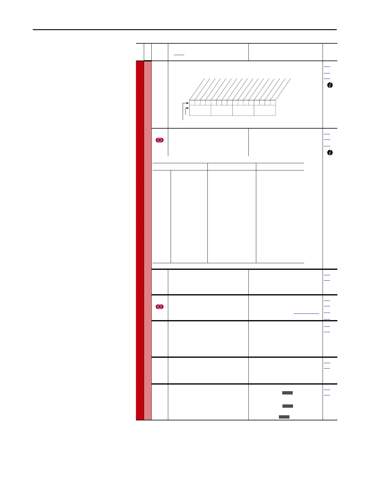
125 [PI Control]
Controls the PI regulator.
080
361…
366
126 [PI Reference Sel]
Selects the source of the PI reference.
(1)
Only Enhanced Control Drives.
Default:
Options:
0“PI Setpoint”
See Table
124…
138
460
127 [PI Setpoint]
Provides an internal fixed value for process
setpoint when [PI Reference Sel] is set to “PI
Setpoint.”
Default:
Min/Max:
Units:
50.00%
±100.00% of Maximum Process
Value
0.01%
124…
138
128 [PI Feedback Sel]
Selects the source of the PI reference.
Default:
Options:
2“Analog In 2”
See
P126 [PI Reference Sel]
.
124…
138
462
463
129 [PI Integral Time]
Time required for the integral component to
reach 100% of [PI Error Meter]. Not functional
when the PI Hold bit of [PI Control] = “1”
(enabled). A value of zero disables this
parameter
Default:
Min/Max:
Units:
2.00 Secs
0.00/100.00 Secs
0.01 Secs
124…
138
130 [PI Prop Gain]
Sets the value for the PI proportional
component.
PI Error × PI Prop Gain = PI Output
Default:
Min/Max:
Units:
1.00
0.00/100.00
0.01
124…
138
131 [PI Lower Limit]
Sets the lower limit of the PI output.
Default:
Min/Max:
Units:
–[Maximum Freq]
–100%
±400.0 Hz
±800%
0.1 Hz
0.1%
124…
138
File C
Group
No.
Parameter Name and Description
See page 14 for symbol descriptions
Values
Related
00x 0xxxxxxxxxxxx
10 01234567891112131415
1=Enabled
0=Disabled
x =Reserved
Bit #
Factory Default Bit Values
PI Enable
PI Hold
PI Reset
Nibble 1Nibble 2Nibble 3Nibble 4
Options P462 [PI Feedback Hi] P463 [PI Feedback Lo]
0
1
2
3…7
8
9
10
11…17
18…20
21
22
23, 24
25
26
27…29
30
31
32
33
“Setpoint”
“Analog In 1”
“Analog In 2”
“Reserved”
“Encoder”
“MOP Level”
“Master Ref”
“Preset Spd1…7”
“DPI Port 1…3”
“Reserved”
“DPI Port 5”
“Reserved”
“Scale Block1”
“Scale Block2”
“Reserved”
“HighRes Ref”
(1)
“CommandedTrq”
(2)
“Torque Est”
(2)
“Torque Amps”
(2)
+100
P322 [Analog In1 Hi]
P325 [Analog In2 Hi]
+P55 [Maximum Freq]
+P55 [Maximum Freq]
+P55 [Maximum Freq]
+P55 [Maximum Freq]
+32767
+32767
P477 [Scale1 In Hi]
P483 [Scale2 In Hi]
+32767 x 2
16
P436 [Pos Torque Limit]
P436 [Pos Torque Limit]
+P28 [Rated Amps]
-100
P323 [Analog In1 Lo]
P326 [Analog In2 Lo]
-P55 [Maximum Freq]
-P55 [Maximum Freq]
-P55 [Maximum Freq]
-P55 [Maximum Freq]
-32676
-32676
P478 [Scale1 In Lo]
P484 [Scale2 In Lo]
-32767 x 2
16
P437 [Neg Torque Limit]
P437 [Neg Torque Limit]
-P28 [Rated Amps]
E C
E C

 Loading...


