36 Rockwell Automation Publication 20A-UM001N-EN-P - July 2013
Chapter 1 Programming and Parameters
SPEED COMMAND (file C)
Speed Trim
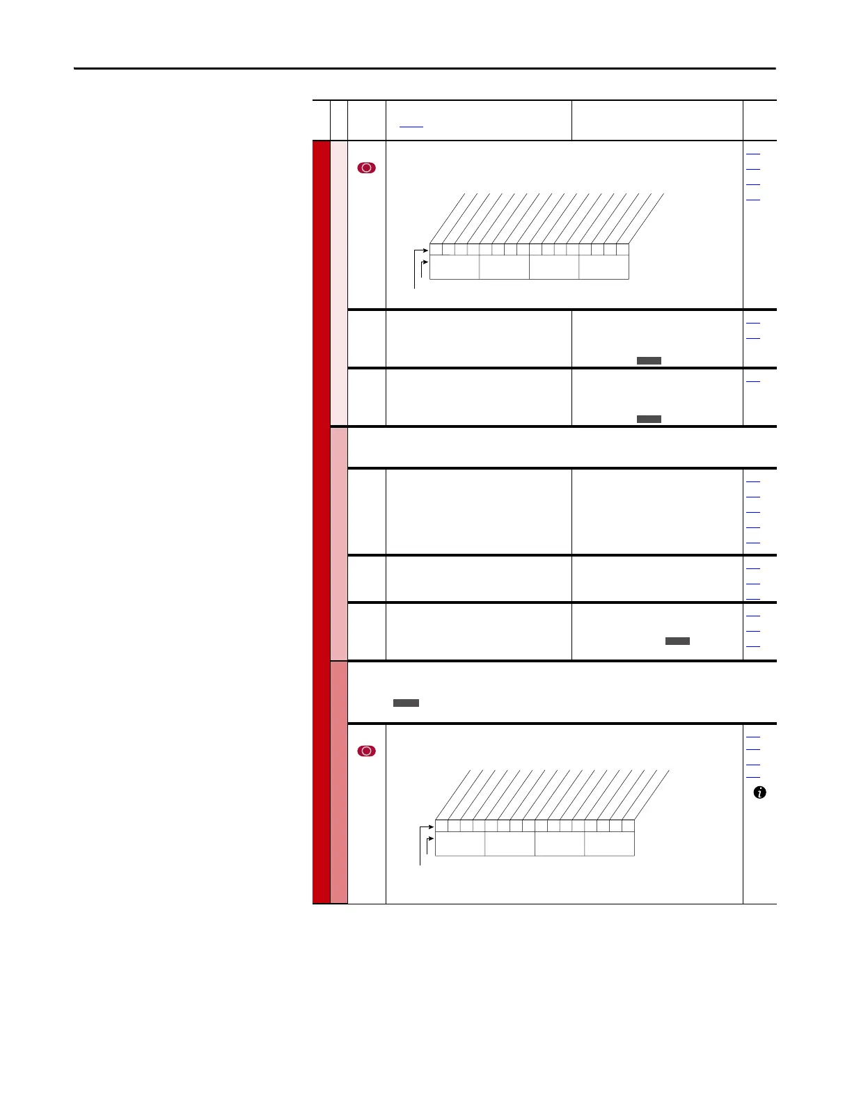
118 [Trim Out Select]
Specifies the speed references to be trimmed. To apply negative trim, P190 [Direction Mode]
must be set to 1 “Bipolar.”
117
119
120
190
119 [Trim Hi]
Scales the upper value of the [Trim In Select]
selection when the source is an analog input.
Default:
Min/Max:
Units:
60.0 Hz
±[Maximum Speed]
0.1 Hz
1 %
082
117
120 [Trim Lo]
Scales the lower value of the [Trim In Select]
selection when the source is an analog input.
Default:
Min/Max:
Units:
0.0 Hz
±[Maximum Speed]
0.1 Hz
1 %
117
Slip Comp
Important: Parameters in the Slip Comp Group are used to enable and tune the Slip
Compensation Regulator. For the Slip Compensation Regulator to control drive operation, set
parameter 080 to 1 “Slip Comp”.
121 [Slip RPM @ FLA]
Sets the amount of compensation to drive
output at motor FLA.
If the value of parameter 061 [Autotune] = 3
“Calculate” changes made to this parameter are
not accepted.
Default:
Min/Max:
Units:
Based on [Motor NP RPM]
0.0/1200.0 rpm
0.1 rpm
044
061
080
122
123
122 [Slip Comp Gain]
Sets the response time of slip compensation.
Default:
Min/Max:
Units:
40.0
1.0/100.0
0.1
080
121
122
123 [Slip RPM Meter]
Displays the present amount of adjustment
being applied as slip compensation.
Default:
Min/Max:
Units:
Read Only
0.0/300.0 rpm
±300.0 rpm
0.1 rpm
080
121
122
Process PI
Important: Parameters in the Process PI Group are used to enable and tune the PI Loop.
For the PI Loop to control drive operation, set parameter 080 to 2 “Process PI”.
124 [PI Configuration]
Sets configuration of the PI regulator.
124
…
138
140…
143
File C
Group
No.
Parameter Name and Description
See page 14 for symbol descriptions
Values
Related
00x 0xxxxxxxxxxxx
10 01234567891112131415
1=Trimmed
0=Not Trimmed
x =Reserved
Bit #
* Enhanced Control Option Only.Factory Default Bit Values
Trim Ref A
Trim Ref B
Add or % *
Nibble 1Nibble 2Nibble 3Nibble 4
E C
E C
E C
0000000000xxxxxx
10 01234567891112131415
1=Enabled
0=Disabled
x =Reserved
Bit #
Factory Default Bit Values
Excl Mode
Invert Error
Preload Mode
Ramp Ref
Zero Clamp
Feedbak Sqrt
Stop Mode
(1)
Anti-Wind Up
(1)
Torque Trim
(2)
% of Ref
(2)
Nibble 1Nibble 2Nibble 3Nibble 4
(1)
Enhanced firmware 1.001 & later.
(2)
Enhanced firmware 2.001 & later.

 Loading...


