Rockwell Automation Publication 20A-UM001N-EN-P - July 2013 79
Troubleshooting Chapter 2
Fault Descriptions
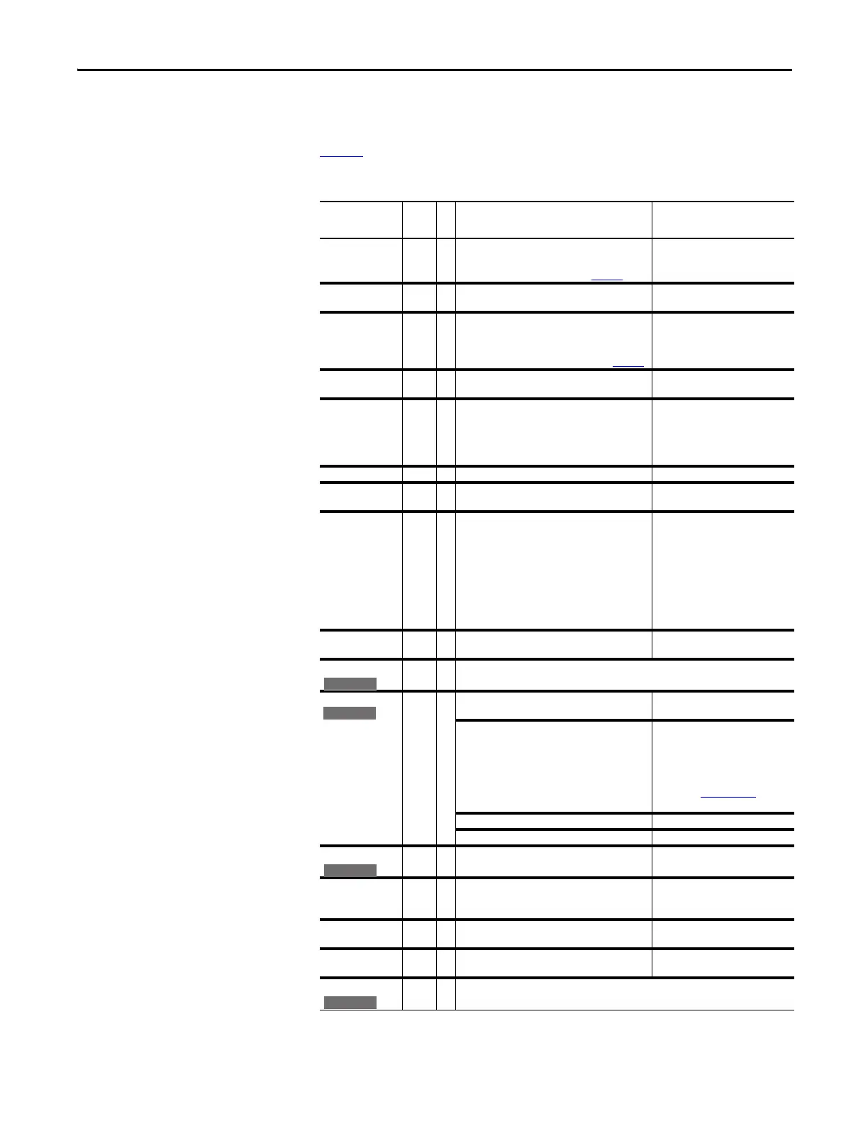
Tab le 1 provides a list of fault messages, descriptions of the cause of the fault, and
corrective action to fix the fault.
Table 1 - Fault Types, Descriptions and Actions
Fault No.
Type
(1)
Description Action
Analog In Loss 29 1
3
An analog input is configured to fault on signal
loss. A signal loss has occurred.
Configure with [Anlg In X Loss] on page 65
.
1. Check the parameters.
2. Check for broken/loose
connections at inputs.
Anlg Cal Chksum 108 The checksum read from the analog calibration
data does not match the checksum calculated.
Replace the drive.
Auto Rstrt Tries 33 3 Drive unsuccessfully attempted to reset a fault
and resume running for the programmed
number of [Flt RstRun Tries].
Enable/Disable with [Fault Config 1] on page 58.
Correct the cause of the fault and
manually clear.
AutoTune Aborted 80 Autotune function was canceled by the user or a
fault occurred.
Restart the procedure.
Cntl Bd Overtemp 55 The temperature sensor on the Main Control
Board detected excessive heat.
1. Check Main Control Board fan.
2. Check surrounding air
temperature.
3. Verify proper mounting/
cooling.
Auxiliary Input 2 1 Auxiliary input interlock is open. Check remote wiring.
DB Resistance 69 The resistance of the internal DB unit is out of
range.
Replace the resistor.
Decel Inhibit 24 3 The drive is not following a commanded
acceleration or deceleration because it is
attempting to limit bus voltage.
1. Verify input voltage is within
drive specified limits.
2. Verify system ground
impedance follows proper
grounding techniques.
3. Disable bus regulation and/or
add dynamic brake resistor
and/or extend deceleration
time.
Drive OverLoad 64 Drive rating of 110% for 1 minute or 150% for 3
seconds has been exceeded.
Reduce load or extend Accel Time.
Drive Powerup 49 No fault displayed. Used as a Power Up Marker in the Fault Queue indicating that the
drive power has been cycled.
Enable Hardware 111 Safe-Off board is not installed and pins 3 and 4 of
the Safe-Off Connector are not jumpered.
Install Safe-Off board or jumper
pins 3 and 4.
If Safe-Off board is installed, verify the hardware
enable jumper is removed.
Locate and remove the enable
jumper on the main control board.
Refer to DriveGuard Safe-Off
Option (Series B) for PowerFlex 40P
and PowerFlex 70 AC Drives,
publication PFLEX-UM003
, for
instructions and location.
Safe-Off board has failed. Replace Safe-Off board.
Hardware enable circuitry failed. Replace control board.
Encoder Loss 91 One or both encoder channel signals is missing. 1. Check Wiring.
2. Replace encoder.
Encoder Quad Err 90 Both encoder channels changed state within one
clock cycle.
1. Check for externally induced
noise.
2. Replace encoder.
Hardware Fault 93 Hardware enable is disabled (jumpered high) but
logic pin is still low.
1. Check jumper.
2. Replace Main Control Board.
Excessive Load 79 Motor did not come up to speed in the allotted
time during autotune.
1. Uncouple load from motor.
2. Repeat Autotune.
Faults Cleared 52 No fault displayed. Used as a marker in the Fault Queue indicating that the fault clear
function was performed.
E C v2
E C
E C v2
E C v2

 Loading...


