Rockwell Automation Publication 20A-UM001N-EN-P - July 2013 81
Troubleshooting Chapter 2
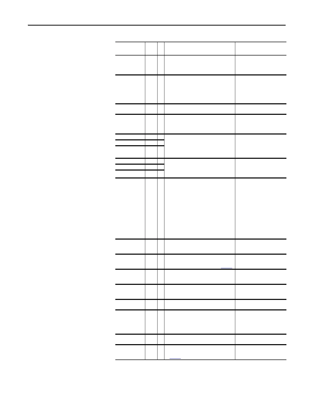
Overspeed Limit 25 1 Functions such as Slip Compensation or Bus
Regulation have attempted to add an output
frequency adjustment greater than that
programmed in [Overspeed Limit].
Remove excessive load or
overhauling conditions or increase
[Overspeed Limit].
OverVoltage 5 1 DC bus voltage exceeded maximum value. Monitor the AC line for high line
voltage or transient conditions. Bus
overvoltage can also be caused by
motor regeneration. Extend the
decel time or install dynamic brake
option.
Parameter Chksum 100 2 The checksum read from the board does not
match the checksum calculated.
1. Restore defaults.
2. Reload User Set if used.
Params Defaulted 48 The drive was commanded to write default
values to EEPROM.
1. Clear the fault or cycle power to
the drive.
2. Program the drive parameters
as needed.
Phase U to Grnd 38 A phase to ground fault has been detected
between the drive and motor in this phase.
1. Check the wiring between the
drive and motor.
2. Check motor for grounded
phase.
3. Replace drive.
Phase V to Grnd 39
Phase W to Grnd 40
Phase UV Short 41 Excessive current has been detected between
these two output terminals.
1. Check the motor and drive
output terminal wiring for a
shorted condition.
2. Replace drive.
Phase VW Short 42
Phase UW Short 43
Port 1…5 DPI Loss 81…
85
DPI port stopped communicating.
A SCANport device was connected to a drive
operating DPI devices at 500k baud.
1. If adapter was not intentionally
disconnected, check wiring to
the port. Replace wiring, port
expander, adapters, Main
Control Board or complete drive
as required.
2. Check HIM connection.
3. If an adapter was intentionally
disconnected and the [Logic
Mask] bit for that adapter is set
to “1”, this fault occurs. To
disable this fault, set the [Logic
Mask] bit for the adapter to “0.”
Port 1…5 Adapter 71…
75
The communications card has a fault. Check DPI device event queue and
corresponding fault information
for the device.
Power Loss 3 1
3
DC bus voltage remained below trigger of
nominal for longer than [Power Loss Time].
Enable/Disable with [Fault Config 1] on page 58
.
Monitor the incoming AC line for
low voltage or line power
interruption.
Pwr Brd Chksum1 104 The checksum read from the EEPROM does not
match the checksum calculated from the
EEPROM data.
Clear the fault or cycle power to the
drive.
Pwr Brd Chksum2 105 2 The checksum read from the board does not
match the checksum calculated.
1. Cycle power to the drive.
2. If problem persists, replace
drive.
Power Down Csum 112 EEPROM data is corrupt on drive power up. Clear the fault or cycle power to the
drive.
Power Unit 70 One or more of the output transistors were
operating in the active region instead of
desaturation. This can be caused by excessive
transistor current or insufficient base drive
voltage.
1. Check for damaged output
transistors.
2. Replace drive.
Replaced MCB-PB 107 2 Main Control Board was replaced and parameters
were not programmed.
1. Restore defaults.
2. Reprogram parameters.
Shear Pin 63 3 Programmed [Current Lmt Val] has been
exceeded. Enable/Disable with [Fault Config 1]
on page 58
.
Check load requirements and
[Current Lmt Val] setting.
Table 1 - Fault Types, Descriptions and Actions (Continued)
Fault No.
Type
(1)
Description Action
 Loading...


