Troubleshooting 4-3
Precharge Board LED Indications
Precharge Board LED indicators are found on Frame 5 & 6 drives. The
LEDs are located above the “Line Type” jumper shown in Figure 1.2.
HIM Indication
The LCD HIM also provides visual notification of a fault or alarm
condition.
Name Color State Description
Power Green Steady Indicates when precharge board power supply is operational
Alarm Yellow Flashing
[1]
[2]
[3]
[4]
[5]
[6]
[7]
Number in “[ ]” indicates flashes and associated alarm
(1)
:
Low line voltage (<90%).
Very low line voltage (<50%).
Low phase (one phase <80% of line voltage).
Frequency out of range or asymmetry (line sync failed).
Low DC bus voltage (triggers ride-through operation).
Input frequency momentarily out of range (40-65 Hz).
DC bus short circuit detection active.
Fault Red Flashing
[2]
[4]
Number in “[ ]” indicates flashes and associated fault
(2)
:
DC bus short (Udc <2% after 20 ms).
Line sync failed or low line (Uac <50% Unom).
(1)
An alarm condition automatically resets when the condition no longer exists
(2)
A fault indicates a malfunction that must be corrected and can only be reset after cycling power.
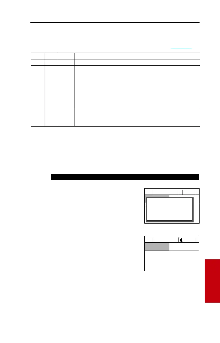
Condition Display
Drive is indicating a fault.
The LCD HIM immediately reports the fault condition
by displaying the following.
• “Faulted” appears in the status line
• Fault number
• Fault name
• Time that has passed since fault occurred
Press Esc to regain HIM control.
Drive is indicating an alarm.
The LCD HIM immediately reports the alarm condition
by displaying the following.
• Alarm name (Type 2 alarms only)
• Alarm bell graphic
F-> Faulted Auto
0.0
Hz
Main Menu:
Diagnostics
Parameter
— Fault — F 5
OverVoltage
Time Since Fault
0000:23:52
F-> Power Loss Auto
0.0
Hz
Main Menu:
Diagnostics
Parameter
Device Select
 Loading...


