Supplemental Drive Information A-17
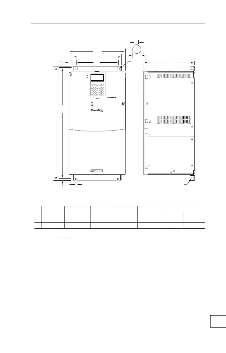
Figure A.5 PowerFlex 700 Frame 5
Dimensions are in millimeters and (inches).
HOT surfaces can cause severe burns
CAUTION
E
12.5
(0.49)
6.5 (0.26)
B
D
A
259.1 (10.20)
Detail
15.0 (0.59)
6.5 (0.26)
37.6 (1.48)
C
Lifting Holes - 4 Places
12.7 (0.50) Dia.
Frame
(1)
A (Max.) BC (Max.) DE
Approx. Weight
(2)
kg (lbs.)
Drive
Drive &
Packaging
5 308.9 (12.16) 644.5 (25.37)
(3)
275.4 (10.84) 225.0 (8.86) 625.0 (24.61) 37.19 (82.0) 42.18 (93.0)
(1)
Refer to Tabl e A. I for frame information.
(2)
Weights include HIM and Standard I/O.
(3)
When using the supplied junction box (100 HP drives Only), add an additional 45.1 mm (1.78 in.)
to this dimension.
 Loading...


