3-10 Programming and Parameters
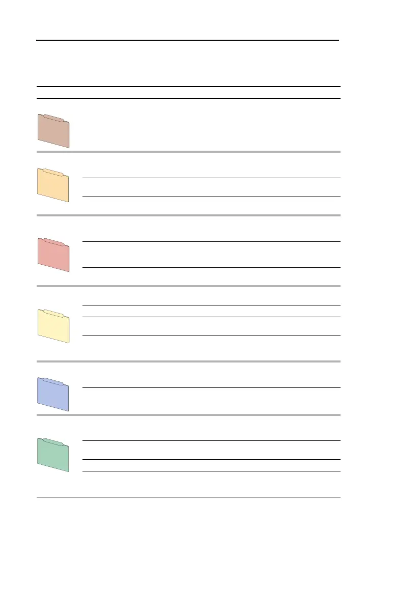
Basic Fan/Pump Parameter View
(1)
– Standard Control Option
Parameter 196 [Param Access Lvl] set to option 3 “Fan/Pump.”
(1)
Only available on Standard Control drives with firmware version 3.001 or above.
File Group Parameters
Monitor Metering Output Freq 001
Commanded Freq 002
Output Current 003
Output Power 007
Elapsed MWh 009
Elapsed Run Time 010
DC Bus Voltage 012
Analog In1 Value 016
Motor Control Motor Data Motor NP Volts 041
Motor NP FLA 042
Motor NP Hertz 043
Motor NP RPM 044
Motor NP Power 045
Mtr NP Pwr Units 046
Torq Attributes Maximum Voltage 054
Maximum Freq 055
Volts per Hertz Start/Acc Boost 069
Run Boost 070
Break Voltage 071
Break Frequency 072
Speed
Command
Spd Mode &
Limits
Speed Mode 080
Minimum Speed 081
Maximum Speed 082
Overspeed Limit 083
Skip Frequency 1 084
Skip Freq Band 087
Speed
References
Speed Ref A Sel 090
Speed Ref A Hi 091
Speed Ref A Lo 092
Discrete
Speeds
Preset Speed 2 102
Dynamic
Control
Ramp Rates Accel Time 1 140
Decel Time 1 142
Load Limits Current Lmt Val 148
Stop/Brake
Modes
Stop Mode A 155
Restart Modes Start At PowerUp 168
Auto Rstrt Tries 174
Auto Rstrt Delay 175
Utility Drive Memory Param Access Lvl 196
Reset To Defalts 197
Language 201
Diagnostics Start Inhibits 214
Dig In Status 216
Dig Out Status 217
Inputs &
Outputs
Analog Inputs Anlg In Config 320
Anlg In Sqr Root 321
Analog In 1 Hi 322
Analog In 1 Lo 323
Anlg In 1 Loss 324
Analog Outputs Anlg Out Config 340
Analog Out1 Sel 342
Analog Out1 Hi 343
Analog Out1 Lo 344
Digital Inputs Digital In1-6 Sel 361-366
Digital Outputs Digital Out1 Sel 380
Digital Out2 Sel 384
Dig Out1 Level 381
Dig Out2 Level 385
Monitor
Motor Control
Speed Command
D
ynam
ic C
ontrol
U
tility
Inputs & O
utputs
 Loading...


