72 Rockwell Automation Publication 20C-PM001F-EN-P - March 2012
Chapter 3 Troubleshooting
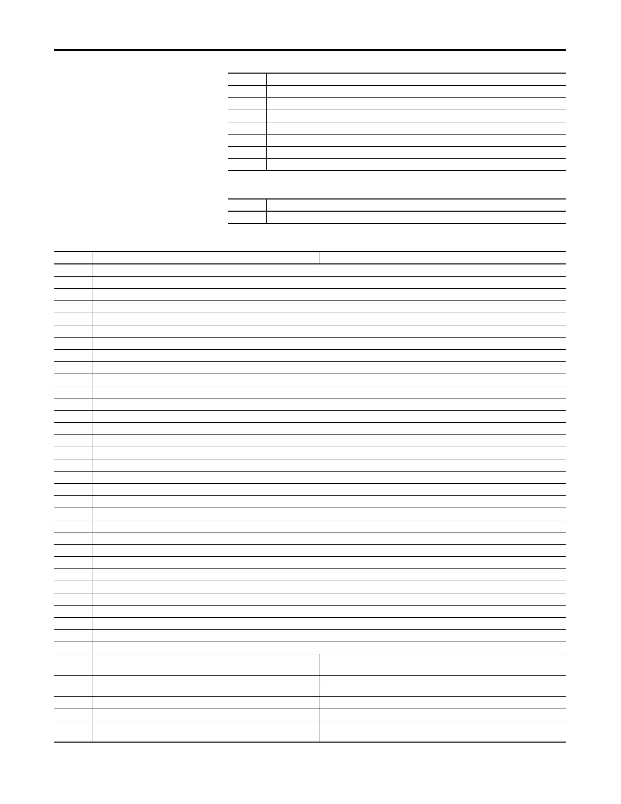
Table 8 - IGBT Over Temperature Fault (F9) Subcode
Table 9 - System Fault (F10) Subcodes
293 There is a heatsink over temperature in the W phase of power unit 1 (typically frame 12 and 14 drives).
304, 305 There is a heatsink over temperature in power unit 2 (typically frame 12 and 14 drives).
306 There is a heatsink over temperature on the Power board of power unit 2 (typically frame 12 and 14 drives).
307 There is a heatsink over temperature in the U phase of power unit 2 (typically frame 12 and 14 drives).
308 There is a heatsink over temperature in the V phase of power unit 2 (typically frame 12 and 14 drives).
309 There is a heatsink over temperature in the W phase of power unit 2 (typically frame 12 and 14 drives).
530 There is a Thermistor over temperature on the Power board (typically frame 12 and 14 drives).
Subcode Description
273 The output transistors have exceeded their maximum operating temperature due to an excessive load.
Subcode Description
Subcode Description Action
273 There is an output phase feedback fault from the motor cables.
275 There is an output phase feedback fault from the U phase motor cable (typically frame 11 and 13 drives).
276 There is an output phase feedback fault from the V phase motor cable (typically frame 11 and 13 drives).
277 There is an output phase feedback fault from the W phase motor cable (typically frame 11 and 13 drives).
1042 There is a disturbance at the ASIC fault-input of the Power board - ribbon cable/software.
1058 There is a disturbance at the ASIC fault-input of the Power board in power unit 1 - ribbon cable/software (typically frame 12 and 14 drives).
1074 There is a disturbance at the ASIC fault-input of the Power board in power unit 2 - ribbon cable/software (typically frame 12 and 14 drives).
1090 There is a disturbance at the ASIC fault-input of the Control board - application software.
1298 There is too much disturbance in system bus traffic on the Power board.
1314 There is too much disturbance in system bus traffic on the Power board in power unit 1 (typically frame 12 and 14 drives).
1330 There is too much disturbance in system bus traffic on the Power board in power unit 2 (typically frame 12 and 14 drives).
1553 The charging relay feedback is not working.
1810 The charging relay control is not set on the Power board.
1826 The charging relay control is not set on the Power board on power unit 1 (typically frame 12 and 14 drives).
1827 The charging relay control is not set configured on the Power board on power unit 2 (typically frame 12 and 14 drives).
2065 The Gate Driver board is without auxiliary voltage (Power ASIC-TRIN).
2067 The Gate Driver board for the U phase is without auxiliary voltage (typically frame 11 and 13 drives).
2068 The Gate Driver board for the V phase is without auxiliary voltage (typically frame 11 and 13 drives).
2069 The Gate Driver board for the W phase is without auxiliary voltage (typically frame 11 and 13 drives).
2080 The Gate Driver board in power unit 1 is without auxiliary voltage. (typically frame 11 and 13 drives).
2081 The Gate Driver board in power unit 1 is without auxiliary voltage (typically frame 12 and 14 drives).
2083 The Gate Driver board for the U phase in power unit 1 is without auxiliary voltage (typically frame 14 drives).
2084 The Gate Driver board for the V phase in power unit 1 is without auxiliary voltage (typically frame 14 drives).
2085 The Gate Driver board for the W phase in power unit 1 is without auxiliary voltage (typically frame 14 drives).
2097 The Gate Driver board in power unit 2 is without auxiliary voltage (typically frame 12 and 14 drives).
2099 The Gate Driver board for the U phase in power unit 2 is without auxiliary voltage (typically frame 14 drives).
2100 The Gate Driver board for the V phase in power unit 2 is without auxiliary voltage (typically frame 14 drives).
2101 The Gate Driver board for the W phase in power unit 2 is without auxiliary voltage (typically frame 14 drives).
2370 The TX fiber optic cable connected to H6 on the 700H Control board is broken.
2594 The fiber optic cable connected to TRIP on the Star Coupler board for power unit 1 is broken (typically frame 12 and 14 drives).
2610 The fiber optic cable connected to TRIP on the Star Coupler board for power unit 2 is broken (typically frame 12 and 14 drives).
2834 The fiber optic cable connected to H5 on the ASIC board is broken.
7767 The safe disable inputs on the 20C-DG1 option board have been in a different
state for more than 5 seconds.
• Verify all connections to the 20C-DG01 option board.
• If this fault and subcode occurs again, replace the 20C-DG1 option board.
8023 A thermistor short circuit has been detected on the 20C-DG1 option board. • Verify the thermistor connections and correct if necessary.
• Verify that the jumper at X10 is in the correct position.
8279 The 20C-DG1 option board has been removed. Set parameter 359 [20C-DG1 Status] to 1"Remove" and then back to 0 "Ready".
8535 There is an EEPROM error on the 20C-DG1 option board. Replace the 20C-DG1 option board.
8791 A supply voltage hardware problem has been detected on the 20C-DG1 option
board.
Replace the 20C-DG1 option board.

 Loading...


