78 Rockwell Automation Publication 20C-PM001F-EN-P - March 2012
Chapter 3 Troubleshooting
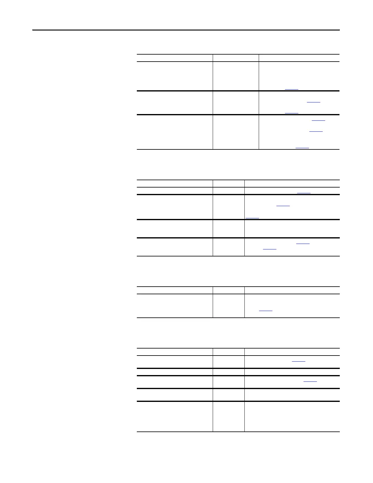
Drive does not Respond to Changes in Speed Command
Motor and/or Drive will not Accelerate to Commanded Speed
Motor Operation is Unstable
Drive will not Reverse Motor Direction
Cause(s) Indication Corrective Action
No value is coming from the source of the
command.
LCD HIM Status Line
indicates “At Speed” and
output is 0 Hz.
1. If the source is an analog input, check
wiring and use a meter to check for
presence of signal.
2. Check [Commanded Speed] for correct
source (see page 20
).
Incorrect reference source has been
programmed.
None 3. Check [Speed Ref Source] for the source of
the speed reference (see page 39
).
4. Reprogram [Speed Ref A Sel] for correct
source (see page 25).
Incorrect reference source is being selected
via remote device or digital inputs.
None 5. Check [Drive Status 1], (see page 38
), bits
12 and 13 for unexpected source selections.
6. Check [Dig In Status], (see page 40) to see if
inputs are selecting an alternate source.
7. Reprogram digital inputs to correct “Speed
Sel x” option (see page 53).
Cause(s) Indication Corrective Action
Acceleration time is excessive. None Reprogram [Accel Time x] (see page 30
).
Excess load or a short acceleration time
forces the drive into current limit, slow, or
no acceleration.
None Check [Drive Status 2], bit 10 to see if the drive is in
Current Limit (see page 38
).
Remove excess load or reprogram [Accel Time x] (see
page 30).
Speed command source or value is not as
expected.
None Check for the proper Speed Command using the steps
outlined in “Drive does not Respond to Changes in
Speed Command” above.
Programming is preventing the drive output
from exceeding limiting values.
None Check [Maximum Speed] (see page 24
) and [Maximum
Freq] (see page 22) to assure that speed is not limited
by programming.
Cause(s) Indication Corrective Action
Motor data was incorrectly entered or
Autotune was not performed.
None 1. Correctly enter motor nameplate data.
2. Perform “Static” or “Rotate” Autotune procedure
(see page 23
).
3. Set gain parameters to default values.
Cause(s) Indication Corrective Action
Digital input is not selected for reversing
control.
None Check [Digital Inx Sel], (see page 53
). Choose correct
input and program for reversing mode.
Digital input is incorrectly wired. None Check input wiring.
Direction mode parameter is incorrectly
programmed.
None Reprogram [Direction Mode], (see page 35
) for analog
“Bipolar” or digital “Unipolar” control.
Motor wiring is improperly phased for
reverse.
None Check for single phasing on the output of the drive.
A bipolar analog speed command input is
incorrectly wired or signal is absent.
None 1. Use meter to check that an analog input voltage is
present.
2. Check wiring.
Positive voltage commands forward direction. Negative
voltage commands reverse direction.

 Loading...


