PowerFlex® 700S Drives - Phase I Control (Frame Sizes 9 & 10) 11
Removing the Skid and Shipping Feet
!
ATTENTION: To guard against personal injury and equipment damage, do not
work under the drive unless the drive is securely mounted on appropriate blocks.
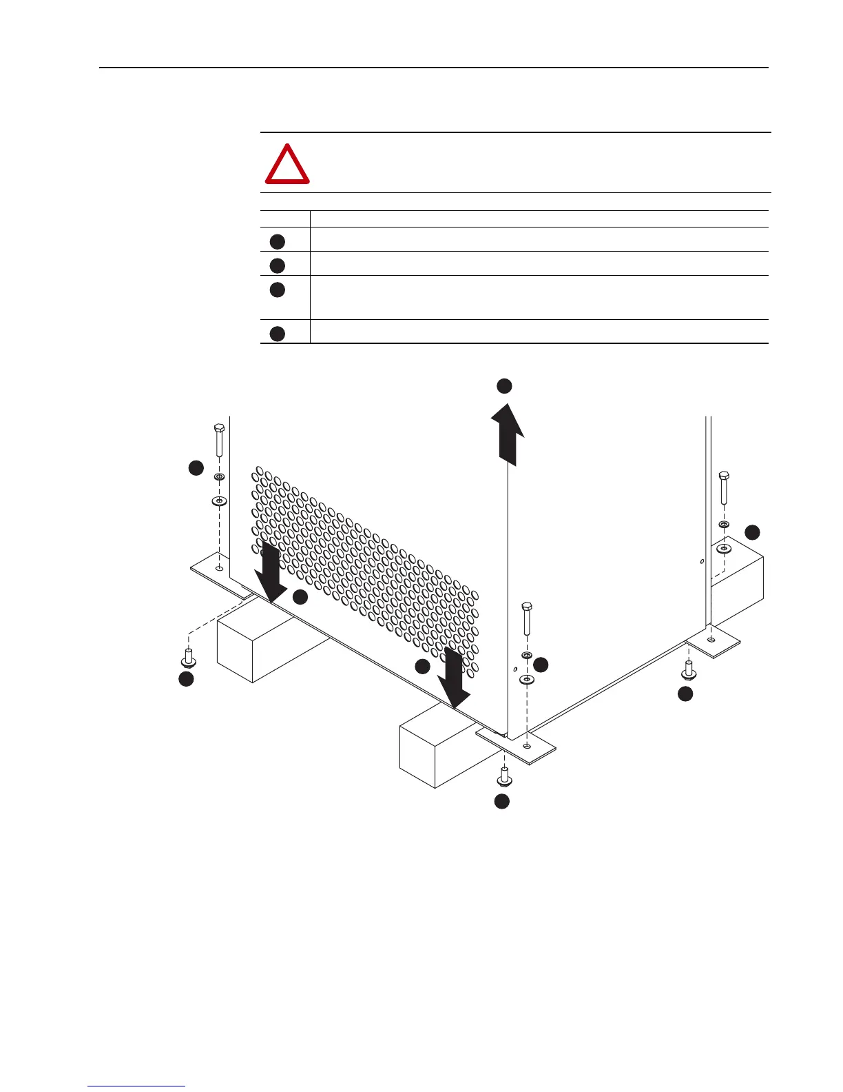
Task Description
Using a 15 mm wrench, remove the hardware which secures the drive to the skid.
Lift the drive off the skid.
Place the drive on proper blocks on a hard, level surface.
The blocks should be approximately 10 cm (4 inches) high.
Using a 17 mm wrench, remove the hardware which secures the feet to the drive and remove the feet.
A
A
A
A
B
A
C
A
C
D
A
B
C
A
A
C
D
D
D

 Loading...


