PowerFlex® 700S Drives - Phase I Control (Frame Sizes 9 & 10) 19
Step 6: Configuring Drive
for Ground System
• For configuring frame 9 size drives for a grounding system, see “Frame 9 Size
Drives” below.
• For configuring frame 10 size drives for a grounding system, see Frame 10 Size
Drives on page 20.
Frame 9 Size Drives
CE frame 9 size drives are equipped with common mode capacitors that are
referenced to ground. Operating a CE frame 9 drive on a resistive ground or
ungrounded distribution system could result in drive damage.
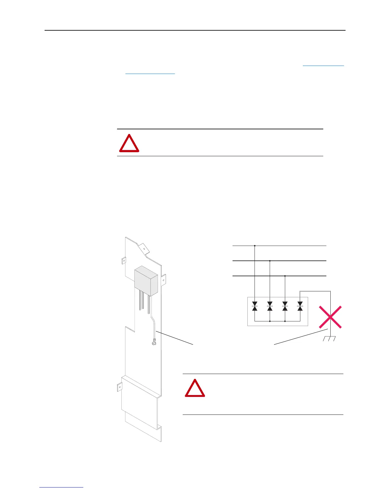
All frame 9 drives (CE and non-CE) are equipped with a Metal Oxide Varistor
(MOV) assembly to provide voltage surge protection. The MOV is designed for
transient surge suppression only (not continuous operation). With a resistive ground
or ungrounded distribution system the phase-to-ground MOV connection could
become a continuous current path. Therefore, you should disconnect the MOV
ground connection when installing a Frame 9 drive on a resistive ground or
ungrounded distribution system. Refer to publication PFLEX-RM001, PowerFlex®
700S with Phase I Control Reference Manual, for information on a resistive ground
or ungrounded system installation.
!
ATTENTION: If you intend to operate a Frame 9 drive on a resistive
ground or ungrounded distribution system, you must order a non-CE
PowerFlex High Power drive.
L1
L2
L3
!
ATTENTION: Risk of equipment damage exists if
this wire contacts other circuits in the drive while the
drive is energized. Insulate the lug on this wire with
several turns of electrical tape and anchor the wire so
it does not contact other circuits.
Disconnect and insulate this wire on a
resistive ground or ungrounded
distribution system
Ground stud on
Cross Plate

 Loading...


