20 PowerFlex® 700S Drives - Phase I Control (Frame Sizes 9 & 10)
Frame 10 Size Drives
Frame 10 size drives are equipped with common mode capacitors that are
referenced to ground. To guard against drive damage, these capacitors should be
disconnected if the drive is installed on a resistive ground or ungrounded
distribution system or on a voltage distribution system greater than 400V AC. For
installations on a resistive ground or ungrounded distribution system, refer to
“Installation on an Ungrounded Distribution System” below. For installations on a
grounded B phase delta system on a voltage distribution system greater than 400V
AC, refer to Installation on a Grounded B Phase Delta System on a Voltage
Distribution System Greater than 400V AC on page 21.
Note: Refer to publication PFLEX-RM002, Reference Manual - PowerFlex®
700S with Phase I Control, for information on a resistive ground or
ungrounded distribution system installation.
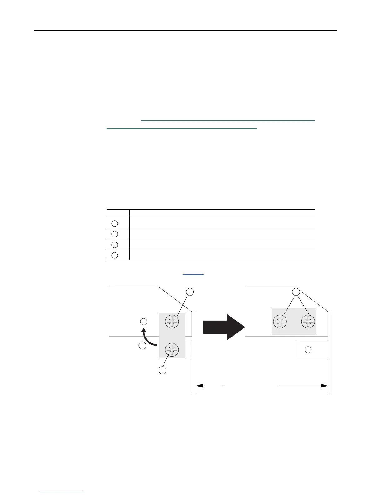
There is one jumper located on the upper-right side of the Rectifying Module.
Installation on a Resistive Ground or Ungrounded Distribution System
1. To disconnect the capacitors, move the jumper shown below.
Continue with step 2 on page 22
.
Task Description
Loosen upper screw
Remove lower screw
Move jumper to horizontal position
Install and tighten screws
A
B
C
D
Rectifying Circuit Board
A
B
C
D

 Loading...


