24 PowerFlex® 700S Drives - Phase I Control (Frame Sizes 9 & 10)
A good example of recommended cable is Belden® 295xx (xx determines gauge).
This cable has four (4) XLPE insulated conductors with a 100% coverage foil and
an 85% coverage copper braided shield (with drain wire) surrounded by a PVC
jacket.
Other types of shielded cable are available, but the selection of these types may limit
the allowable cable length. Particularly, some of the newer cables twist 4 conductors
of THHN wire and wrap them tightly with a foil shield. This construction can
greatly increase the cable charging current required and reduce the overall drive
performance. Unless specified in the individual distance tables as tested with the
drive, these cables are not recommended and their performance against the lead
length limits supplied is not known.
Armored Cable
Cable with continuous aluminum armor is often recommended in drive system
applications or specific industries. It offers most of the advantages of standard
shielded cable and also combines considerable mechanical strength and resistance to
moisture. It can be installed in concealed and exposed manners and removes the
requirement for conduit (EMT) in the installation. It can also be directly buried or
embedded in concrete.
Because noise containment can be affected by incidental grounding of the armor to
building steel (see Chapter 2. “Wire Types,” of publication DRIVES-IN001, Wiring
and Grounding Guidelines for Pulse Width Modulated (PWM) AC Drives) when the
cable is mounted, it is recommended the armored cable have an overall PVC jacket.
Interlocked armor is acceptable for shorter cable runs, but continuous welded armor
is preferred.
Best performance is achieved with 3 spaced ground conductors, but acceptable
performance below 200 HP is provided via a single ground conductor. See Table B
.
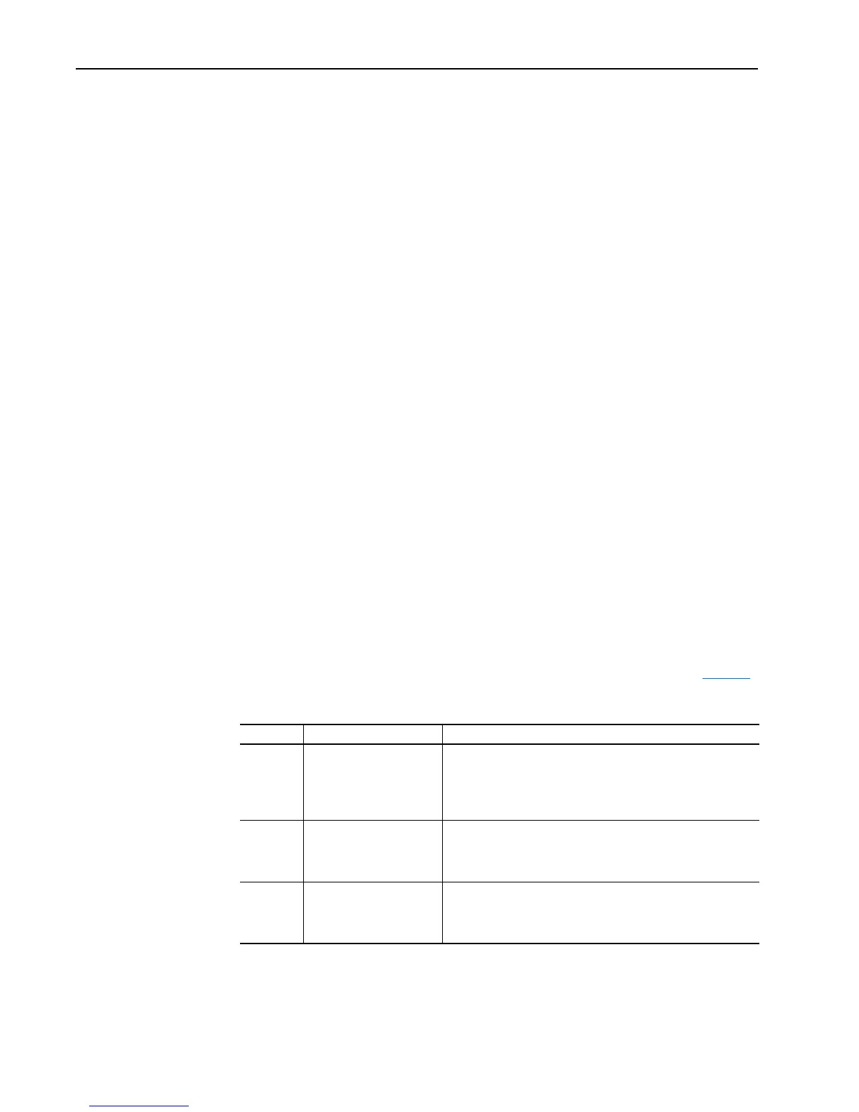
Table B Recommended Shielded / Armored Cable
Location Rating/Type Description
Standard
(Option 1)
600V, 90° C (194° F)
XHHW2/RHW-2
Anixter B209500-B209507,
Belden 29501-29507, or
equivalent
• Four tinned copper conductors with XLPE insulation.
• Copper braid/aluminum foil combination shield and tinned copper
drain wire.
• PVC jacket.
Standard
(Option 2)
Tray rated 600V, 90° C (194°
F) RHH/RHW-2
Anixter OLF-7xxxxx or
equivalent
• Three tinned copper conductors with XLPE insulation.
• 5 mil single helical copper tape (25% overlap min.) with three bare
copper grounds in contact with shield.
• PVC jacket.
Class I & II;
Division I & II
Tray rated 600V, 90° C (194°
F) RHH/RHW-2
Anixter 7V-7xxxx-3G or
equivalent
• Three bare copper conductors with XLPE insulation and
impervious corrugated continuously welded aluminum armor.
• Black sunlight resistant PVC jacket overall.
• Three copper grounds on #10 AWG and smaller.

 Loading...


