PowerFlex® 700S Drives - Phase I Control (Frame Sizes 9 & 10) 33
Class 1 LED Product
Refer to publication number 1756-TD008, SynchLink System Design Guide, when
planning and connecting the SynchLink network.
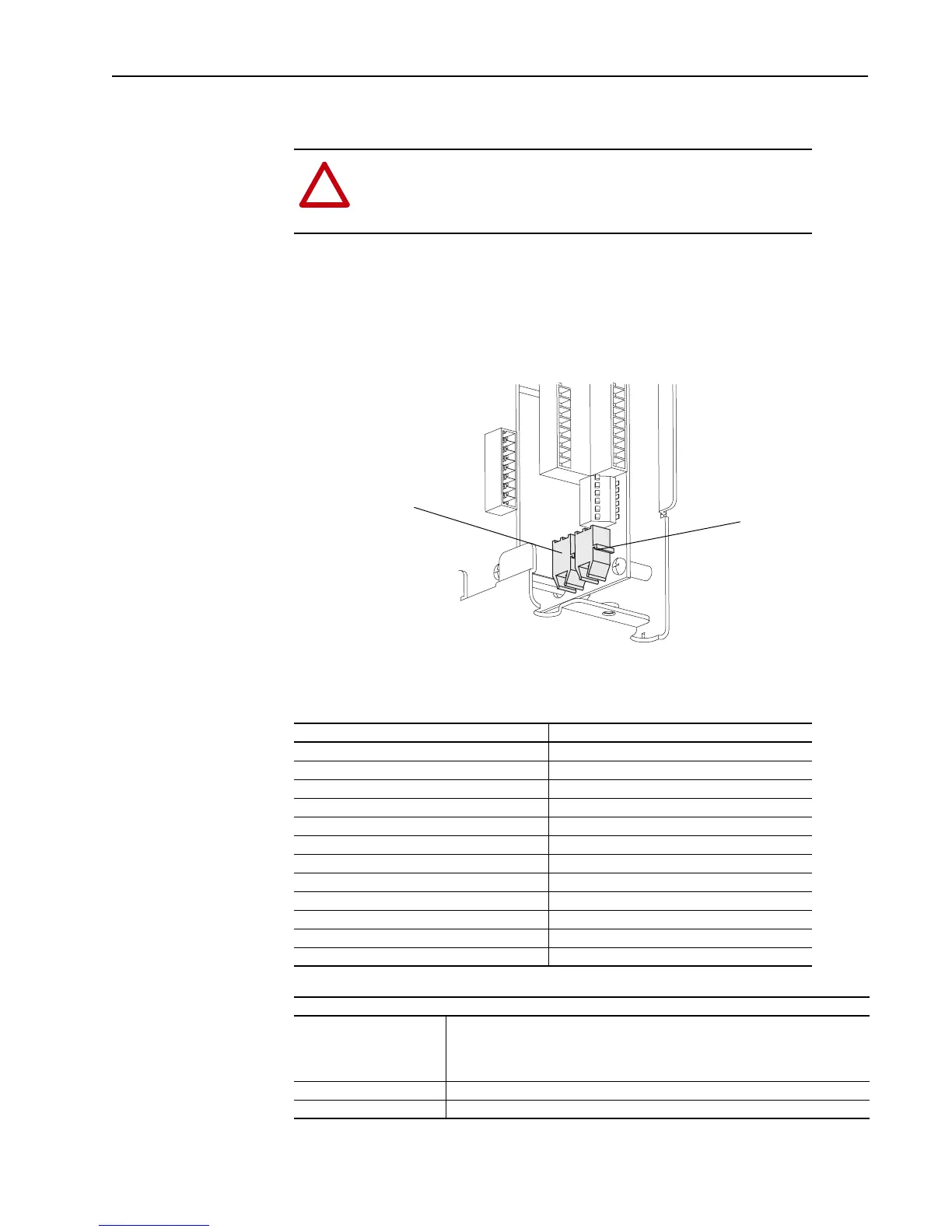
Connect cables to J9 (receive) and J8 (transmit) connectors on the bottom of the
Main Control Board. Push the plug into the socket until it produces an audible click.
Important: Do not overtighten tie-wraps.
Table G SynchLink Cables and Accessories
Table H Fiber Optic Cable Assembly
!
ATTENTION: Hazard of permanent eye damage exists when using
optical transmission equipment. This product emits intense light and
invisible radiation. Do not look into module ports or fiber optic cable
connectors.
J9 (Receive)
J8 (Transmit)
Description Cat. No.
2 x 1 M Fiber Optic Link 1403-CF001
2 x 3 M Fiber Optic Link 1403-CF003
2 x 5 M Fiber Optic Link 1403-CF005
10 M Fiber Optic Link 1403-CF010
20 M Fiber Optic Link 1403-CF020
50 M Fiber Optic Link 1403-CF050
100 M Fiber Optic Link 1403-CF100
250 M Fiber Optic Link 1403-CF250
500 M Fiber Optic Bulk 1403-CFBLK
SynchLink Fiber-Hub, 1 input, Base 1751-SLBA
SynchLink Fiber-Hub, 4 output, “Star” Splitter 1751-SL4SP
SynchLink Bypass Switch 1751-SLBP/A
Specification
Connecting Cables 200/230 micron HCS (Hard Clad Silica)
• Versalink V-System
• Lucent Technologies,
• Specialty Fibers Technology Division
Maximum Cable Length 300 meters with no more than one splice or one adapter
Minimum Cable Length 1 meter

 Loading...


